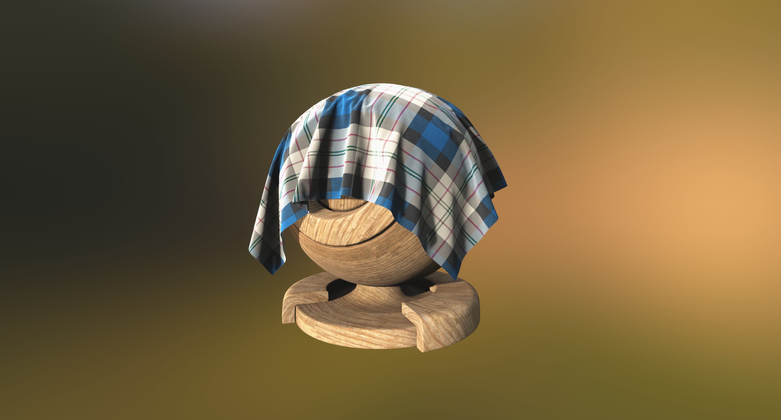
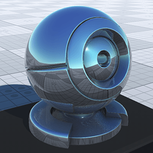
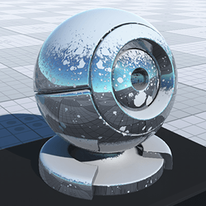
mesh_base
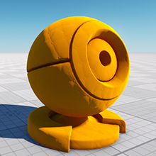
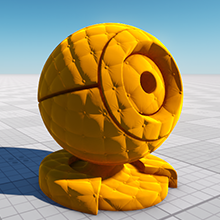
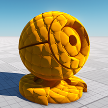
A mesh_base material is a physically based material featuring PBR (physically-based rendering) and SSR (screen space reflections) technologies. It provides the realistic reflections and lighting model. The material is available in the Materials list and is used as the default one.
Options available in the States tab enable different features thus activating additional textures and their parameters.
Workflows#
The main thing about the PBR material is a workflow. There are two workflows for Unigine PBR materials: Metalness and Specular. The specular workflow works with the old standard of textures that was used in the mesh_base material (diffuse, specular, gloss). Metalness works with the new standard of textures (albedo, metalness, roughness).
We've kept the Specular workflow to make it easier to upgrade your projects that have the old texture standard.
We strongly recommend to use the Metalness workflow for creating materials in new projects as it uses a less number of texture channels, and material parameters of the Metalness workflow are more similar to material parameters of the real world.
By using the Workflow field you can specify the workflow of the material:
- Metalness — with the new standard of textures.
- Specular — with the old standard of textures.
Deferred Buffers#
Deferred Buffers option specifies if deferred buffers of the material should be filled.
Multiple Environment Probes#
Multiple Environment Probes option specifies if several environment probes affect a transparent object and map their cubemaps to this object. This option should be enabled for a transparent object to be affected by baked voxel GI.
- This option is available for transparent materials only (except materials with the Alpha test transparency preset).
- Rendering of Multiple Environment Probes must be enabled via Rendering -> Transparent -> Multiple Environment Probes.
 |
 |
Multiple Environment Probes is on |
Multiple Environment Probes is off |
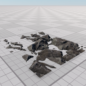
Terrain Lerp#
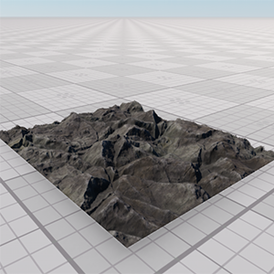
Terrain Lerp allows marking material to make objects be covered by projected textures of the ObjectLandscapeTerrain or ObjectTerrainGlobal.
- This option is not available for a terrain curved using a geodetic pivot.
- For appropriate projection, the position of an object should be within the borders of the Global Terrain along the X and the Y axis.
 |
 |
Terrain Lerp is off |
Terrain Lerp is on |
Emission#
Emission simulates glow from extremely bright surfaces, therefore imitating real light sources and highlights. It can be used, for example, to simulate a glow of distant objects. Enabling the option activates an additional emission texture.
Emission Texture#
Emission map stores information about the light emission. It is blended additively over a texture, so areas which do not glow at all should be pure black on the glow map, and any brighter colors will appear to be emitting light.
|
|
|
Emission state disabled
|
Emission state enabled, with emission texture
|
The texture is 3-channeled.
- RGB values store information about a glowing color.
Emission Parameters#
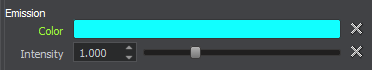
Color#
Color is a color picker to choose a color multiplier for the emission texture.
Scale#
Scale is a coefficient to scale emission texture intensity. The higher the value, the lighter and brighter light areas of the emission texture are.
Cross Section#
Cross Section enables rendering of cross-sections of an object to which the material is applied (can be useful for complex CAD models).
A cross-section of the object is created by the near clipping plane of the camera (player) viewing frustum that cuts this object. If the camera's near clipping plane is oblique, you can change its obliqueness and, therefore, change transformation of the cross-section. All plane sections are highlighted with a color.
Cross Section Color#
Cross Section Color specifies a color for a plane section (an area created by a plane cutting through a solid).
Ambient Occlusion#
Ambient Occlusion (SSAO) is a real-time imitation of the diffuse indirect light and its shadows.
Enabling the option activates the Ambient occlusion field that specifies which UV coordinates of the mesh will be used for textures.
Ambient Occlusion Texture#
Ambient occlusion (AO) texture modulates the global environment illumination, for example, when an object is lighter at the top from sky above, and darker at the bottom from the ground below.
|
|
|
Without AO texture
|
With AO texture
|
The texture uses only R channel.
Ambient Occlusion Parameters#
Auxiliary Buffer#
Auxiliary activates the auxiliary texture and parameters.
Auxiliary Texture#
Auxiliary texture is a texture that used for auxiliary rendering pass.
Auxiliary Color#

Auxiliary color parameter specifies the constant color for the auxiliary pass.
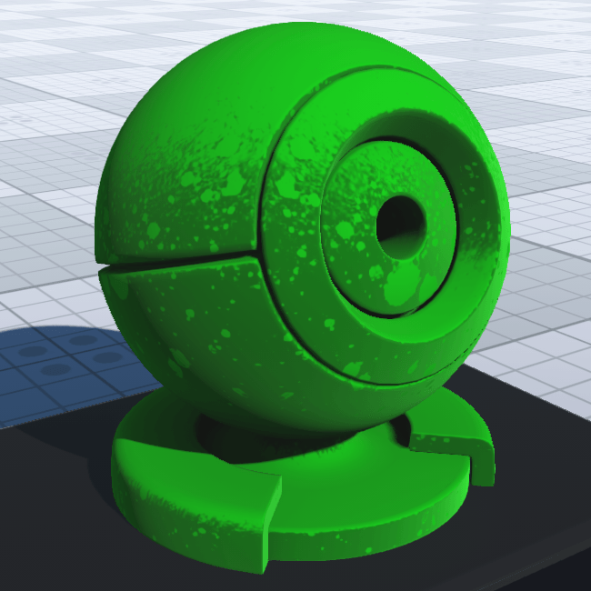
Vertex Color#
The vertex color is a color assigned to each vertex of the 3D model in any third party 3D editor. After being imported to Unigine, such model can be used in a number of ways allowing you to reduce the amount of used texture and broaden the diversity of the final materials.
The Vertex color checkbox enables an additional Vertex color options field used for per channel modulation of the albedo, AO, emission, detail and auxiliary textures.
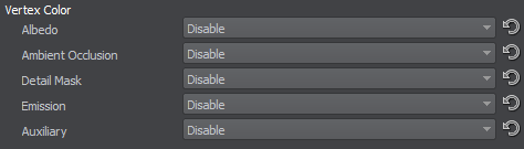
For the AO and detail textures, you can choose which texture channel (R, G, B or A) to use. For albedo, emission, and auxiliary textures, RGB channels are used simultaneously.
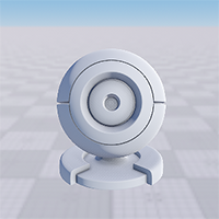
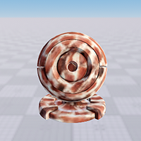
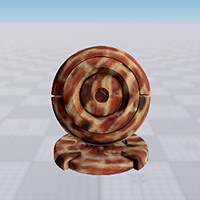
For example, using the vertex color of the albedo texture allows you to create a detail material. At the pictures below there is a model containing vertex colors (brown spotted). Left to right:
- No texture is used, Vertex color is disabled.
- No texture is used, Vertex color is enabled, the Albedo RGB mode is used.
- The diffuse texture (light wood) is assigned, Vertex color is enabled, Albedo RGB mode is used.
|
|
|
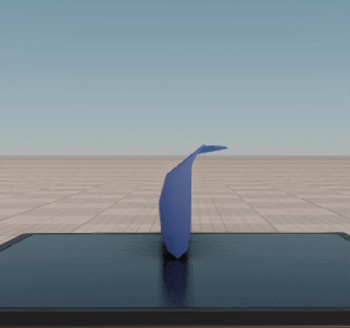
Planar Reflections#
The mesh_base material features a dynamic planar reflection technique for transparent materials (Alpha Blend, Additive, Multiplicative transparency presets). The reflecting power of the material depends on two parameters: metalness and roughness.
By using planar reflection options, you could create flat mirrors and flat dynamic reflective surfaces: parquet, flat varnished surfaces, etc.

The engine renders dynamic reflections for planar reflection by computing the position of the reflection camera. Reflection camera represents a camera on the other side of the reflective surface: the distance from reflector to camera is the same for real camera and reflection camera.
Planar reflections don't reflect each other: they render environment cubemap instead. Also, planar reflections miss post-effects.
To enable planar reflections for the transparent material, click the Planar Reflection checkbox (available for Alpha Blend, Additive, and Multiplicative transparency presets). After enabling the option, the additional Planar Reflection group becomes available. Ensure that the material has dynamic reflections. If not, tune the following parameters: Metalness and Roughness for metalness workflow, Microfiber and Gloss for specular workflow.

Map Size#
Specifies the size of the reflection map: the higher the value, the better the quality.
Available sizes of the map are:
- 128 — creates a reflection image with 128x128 resolution.
- 256 — creates a reflection image with 256x256 resolution.
- 512 — creates a reflection image with 512x512 resolution.
- 1024 — creates a reflection image with 1024x1024 resolution.
- 2048 — creates a reflection image with 2048x2048 resolution.
- 4096 — creates a reflection image with 4096x4096 resolution.
- Quart height — creates a reflection image with the resolution height/4 xheight/4, where height is an application window height.
- Half height — creates a reflection image with the resolution height/2 xheight/2, where height is an application window height.
- Height — creates a reflection image with the resolution height xheight, where height is an application window height.
Two Sided#
The Two Sided option enables a two-sided planar reflection.
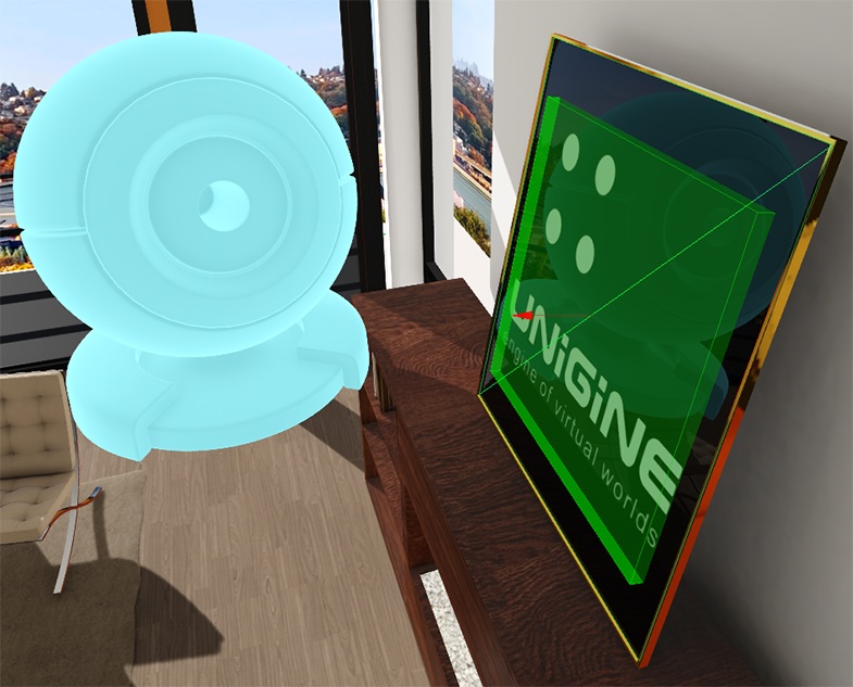
Show Pivot#
The Show Pivot option shows the pivot plane, which shows the direction of reflective surface. By specifying the direction of planar reflection, you can create a reflection surface even if it was exported at an angle.
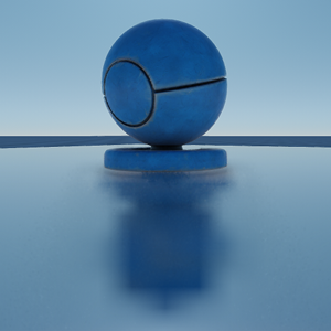
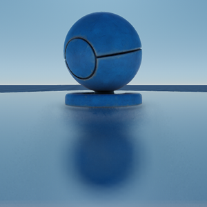
Blur#
The Blur option enables blurring of the planar reflection texture making reflections look more plausible.
 |
 |
Blur disabled |
Blur enabled |
Planar Reflection Parameters#
The set of planar reflection parameters (available on the Parameters tab):
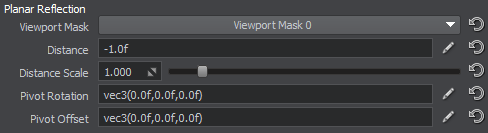
Viewport Mask#
Viewport Mask specifies the viewport mask of the reflection camera.
Distance#
Distance from the reflection camera to the reflected object. In other words, the distance equals the distance from camera to the reflective surface plus the distance from object to reflective surface.
Distance Scale#
Global distance multiplier for the reflection visibility distance. Distance Scale is applied to the distance measured from the reflection camera to the node's (surface's) bound.
This option allows a developer to increase rendering performance by using less detailed LODs for reflections or reducing the number of reflected nodes.
Increasing the value leads to decreasing performance.
Pivot Rotation#
Pivot Rotation specifies the rotation of the reflection pivot point.
Pivot Offset#
Pivot offset specifies the position of the pivot point.
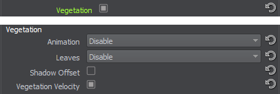
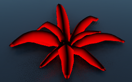
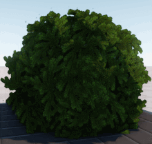
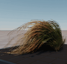
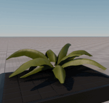
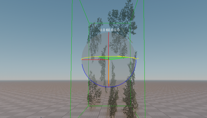
Vegetation#
The mesh_base material allows creating materials for vegetation foliage and stems. Enabling the Vegetation checkbox activates a set of additional animation and geometry parameters.
Animation#
Enables vegetation animation. The available values are:
- Disable — the material is static.
- Default — animation of stems and leaves is enabled and can be controlled by the animation parameters.
- Field — animation of stems and leaves is enabled, can be controlled by the animation parameters, and the material's animation parameters can be affected by the animation field.
Leaves#
Leaves specifies the way to render the leaves geometry:
- Disable — leaves are not rendered.
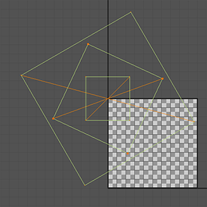
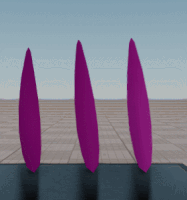
Billboard — leaves are rendered as billboards that always face the camera. This is the most performance-friendly way of animating distant vegetation. Animation uses UV channel 2 of an object as follows: in the UV grid, [0,1] is the pivot point for the billboard's movements, and the billboard's size can be changed by scaling the polygon in the UV channel.
If a billboard object uses the below UV map for animation, it would be represented by three objects rotating around their centers.
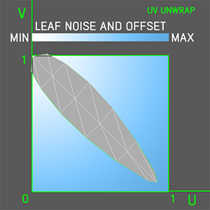
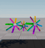
Geometry UV-based — leaves are rendered as standard polygons. Animation uses UV channel 2 of an object as follows: in the UV grid, [0,1] is the pivot point for the object's movements and the stiffest part of the object, and towards [1,0], the object becomes more flexible.
In the diagram below, the stiffest part of the object is against the white background, and the most flexible — against the blue background.
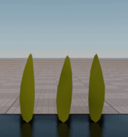
Geometry Vertex Color based — leaves are rendered as standard polygons; vertex colors are used for animation. Vegetation movements are configured using RGB channels as follows:
Red channel is used for animation of smaller or peripheral parts of vegetation (leaves). Bright parts are animated, and dark parts are not animated. 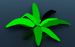
Green channel is used to define the movement order for branches in order to desynchronize them. The movement sequence starts from the brightest element to the darkest. 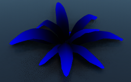
Blue channel is used to define which parts of branches can be bent. Brigher parts indicate bendable portions, and darker parts — stiff portions.
Examples#
 |
 |
 |
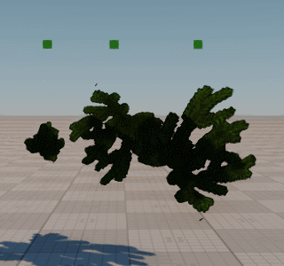
| Animation -> Enable Leaves -> Billboard |
Animation -> Enable Leaves -> Geometry UV-based |
Animation -> Enable Leaves -> Geometry Vertex Color based |
Shadow Offset#
Shadow offset enables an offset parameter for leaves shadows.
Vegetation Velocity#
Vegetation Velocity enables rendering of vegetation animations to the velocity buffer. Can be used to improve TAA and Motion Blur result when necessary. In other cases you can disable this option to gain performance (as objects with this option enabled are rendered twice).
Vegetation Parameters#
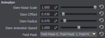
Animation Parameters#
Animation parameters are available on the Parameters tab if the Animation option is enabled.
-
Stem Noise Scale — a coefficient to scale spatial noise that diversifies the movement direction of vegetation stems. This coefficient should be identical for the stem and the leaves that are related to this stem to synchronize their movement.
 Stem Noise Scale: 0.0, 0.5, and 1.0
 -
Stem Offset — a coefficient to scale an amplitude of horizontal movement for the vegetation stem. This coefficient should be identical for the stem and the leaves that are related to this stem to synchronize their movement.
 Stem Offset: 0.5, 1.0, and 1.5
 -
Stem Radius — a coefficient to scale an amplitude of vertical movement for the vegetation stem. This coefficient should be identical for the stem and the leaves that are related to this stem to synchronize their movement.
 Stem Radius: 0.0, 5.0, and 10.0
 -
Stem Animation Speed — a coefficient to scale the speed of stem movements. This coefficient should be identical for the stem and the leaves that are related to this stem to synchronize their movement.
 Stem Animation Speed: 0.0, 4.0, and 8.0
 - Field Mask — a mask that specifies an area of the animation field to be applied to stems and leaves (if rendered). This mask must match the field mask of the animation field.
NoticeThe Field Mask parameter is available only if the Animation state is set to Field.
If leaves are rendered, the following animation parameters are also available:
-
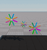
Leaves Noise Scale — a coefficient to randomize the orientation and direction of rotation for leaves (seen only on several nodes with the same material). By the minimum value of 0, all leaves are synchronized in their movement. Higher values make leaves randomly move in different directions.
 Leaves Noise Scale: 50.0Leaves Noise Scale:
1.0, 10.0, and 20.0Leaves Noise Scale: 0.0 and 3.0 -
Leaves Offset — a coefficient to scale leaves rotation amplitude. By the minimum value of 0, leaves do not move at all. Higher values make leaves move with a greater amplitude.
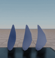
 Leaves Offset: 1.785Leaves Offset:
0.06, 0.08, and 0.1Leaves Offset: 0.05 and 0.1 -
Leaves Animation Speed — a coefficient to scale the speed of leaves rotation. By the minimum value of 0, leaves do not move at all. Higher values make leaves move faster.
 Leaves Animation Speed:
0.765 and 2.287Leaves Animation Speed:
0.0, 1.0, and 4.0Leaves Animation Speed: 2.0 and 5.0 -
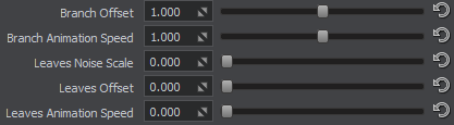
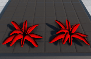
Branch Offset — a coefficient to scale the rotation amplitude for a whole branch. Available for the vertex color based geometry only.
 Branch Offset: 0.1 and 0.3
 -
Branch Animation Speed — a coefficient to scale the rotation speed for a whole branch. Available for the vertex color based geometry only.
 Branch Animation Speed: 3.0 and 8.0
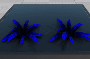
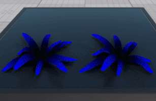
Shadow Offset#
The parameter sets an offset of leaves shadows. Available in the Parameters tab when the Shadow Offset option is enabled.
 |
 |
Shadow offset = 0.0 |
Shadow offset = 0.1 |
Mip Bias#
Mip bias activates an additional Mip Bias parameter. It is used to adjust MIP mapping.
Mip Bias Parameter#

Coefficient for MIP maps adjustment.
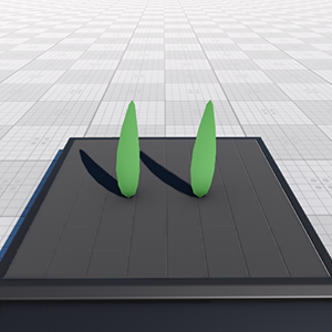
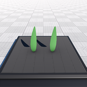
2D Noise#
2D noise enables a spatial color noise based on a 2D texture. Enabling the option activates the following texture and parameters:
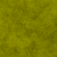
2D Noise Texture#
A color noise 2D texture.
2D Noise Parameters#
Intensity#
Noise texture intensity. By the maximum value of 1, the color noise is fully visible.
 |
 |
 |
Intensity = 0.0 |
Intensity = 0.5 |
Intensity = 1.0 |
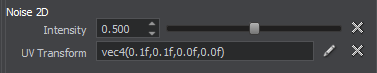
UV Transform#
Noise texture native coordinates transformation represented by a vector of the four float components.
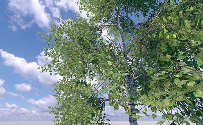
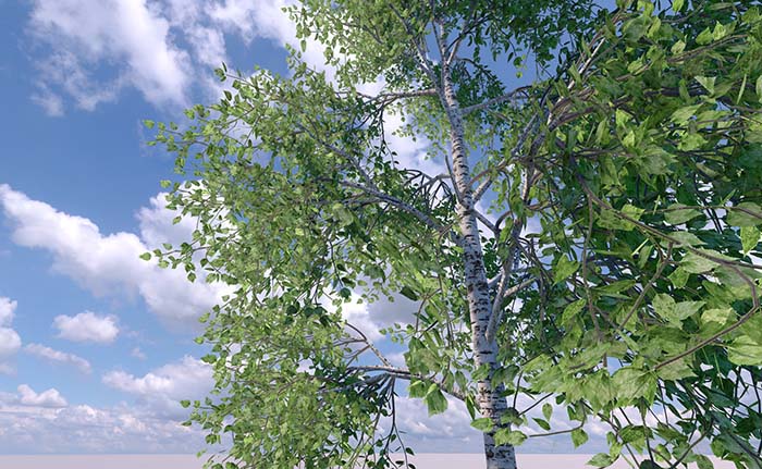
3D Noise#
3D noise specifies if additional spatial noise and color gradient textures will be added. These textures add a random color variation to leaves.

|

|
|
Disabled 3D noise
|
Enabled 3D noise
|
Enabling the option activates the following textures and parameters:
3D Noise Textures#
3D Noise Texture#
A single channeled spatial color noise texture used to randomize the coloring of leaves according to the gradient color texture.

Color Gradient#
A gradient texture that modulates leaves colors (for example, from bright green to yellow). 0.5 means the texture does not affect leaf color. Higher values lighten the colors (are added). Lower values darken the colors (are subtracted).

3D Noise Parameters#
Intensity#
Noise texture intensity. By the maximum value of 1, the color noise is fully visible.
|
 |
 |
Intensity = 0.0 |
Intensity = 0.5 |
Intensity = 1.0 |
UV Transform#
Noise texture native coordinates transformation along X, Y and Z axes. A vector of the three float components:
- By high values, color blobs are small in size (for example, several blobs per leaf). Tiles of the spatial noise texture are small and repeat often
- By low values, color blobs are big (for example, several blobs for the whole tree). Tiles of the spatial noise texture are big and repeat a few times
|
|

|
|
UV transform = vec3(0.1)
|
UV transform = vec3(0.01)
|
Detail Rendering#
Detail rendering activates a set of textures (diffuse, normal, specular for the Specular workflow; albedo, normal and shading for Metalness workflow) to form a material layer. It is applied for bringing detailing to the material.
Available options are (when the state is enabled):
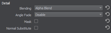
- Blending — the type of the detail material blending.
- Alpha blend — an alpha blending mode.
- Overlay - depending on the base texture (diffuse or albedo) color, the base and detail textures colors are either multiplied (for dark color pixels) or screened (for light color pixels), which leads to the contrast increase while preserving highlights and shadows. Grey pixels are not effected at all.
- Multiply — the base texture (diffuse or albedo) color is multiplied by the detail texture color, resulting in darker colors. White pixels are not effected at all.
NoticeIf detail textures are not visible enough in the resulting image, try increasing its color scale parameter (Diffuse or Albedo).
 Alpha blending modeOverlay modeMultiply mode
 - Angle fade — detail angle fade.
- Disable — disable overlapping of the base material.
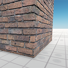
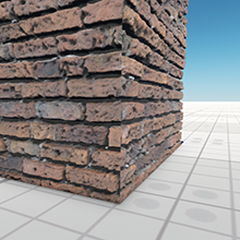
- Object transform (overlap) — overlap the base material by using the object transformation (detail textures will be rotated with the mesh). This option can be used to create stone material with moss, rust and corrosion atop.

 Base albedo textureDetail albedo texture
 - World transform (overlap) — overlap the base textures by using the world transformation (no matter if you rotate the object, the detail textures will always be projected atop). This option can be used to create stone material with moss, rust and corrosion atop.
 Base albedo textureDetail albedo textureNoticeThese two overlap options (Overlap (object transform) and Overlap (world transform)) replaced the old mesh_overlap_base material.
- Mask — a flag indicating that a texture mask is used for blending base and detail materials selectively (the detail textures will be shown according to the mask).
NoticeEnabling the mask activates the Detail mask field that specifies which UV coordinates of the mesh will be used for the detail mask.This option replaced the old mesh_layer_base material.
- Normal Substitute — enabling this flag makes the detail normal texture overlap the base normal texture. If disabled, the base and detail normal maps are combined.
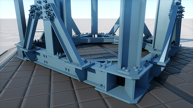
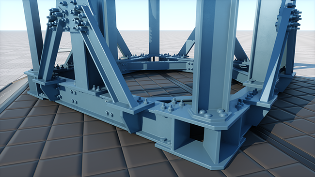
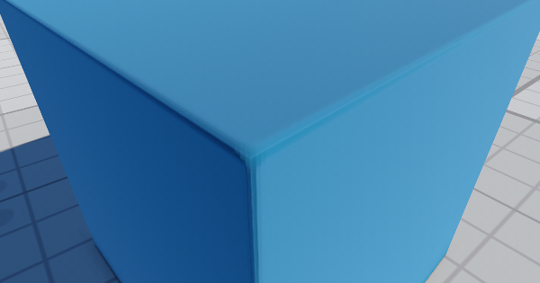
Procedural Effects#
SSBevel#
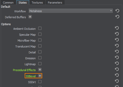
SSBevel enables rendering of the screen-space bevels for the material.
Procedural Texture#
Texture used for procedural effects, such as SSBevel and SSDirt.
The texture is 3-channeled:
SSBevel Parameters#
Scale#
Scale is a multiplier for the bevel's radius.
SSBevel UV Transform#
SSBevel UV Transform sets coordinates transformation for the SSBevel map. To specify which UV coordinates of the mesh should be used for the bevel texture, go to the States tab and set the SSBevel value in the UV Mapping section.
Triplanar Blend#
Triplanar Blend - triplanar blending factor.
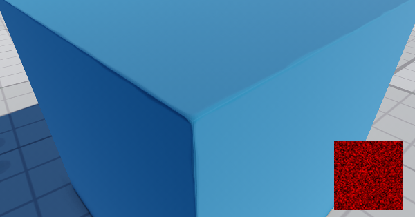
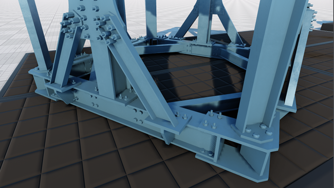
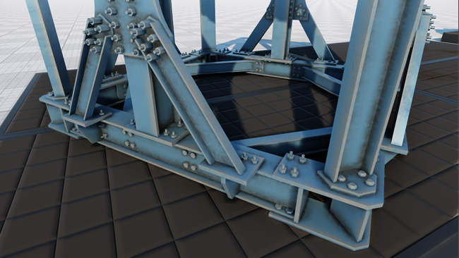
SSDirt#
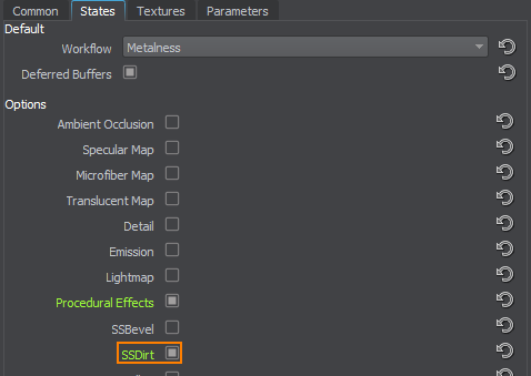
SSDirt enables rendering of the SSDirt effect for the material, allowing you to simulate worn scratched edges and accumulation of dirt and dust in cavities.
This effect uses the Procedural texture described above.
SSDirt Parameters#
Cavity Scale#
Scale factor for the SSDirt effect in concave areas. Higher values result in more pronounced effect in slits and cavities.
Convexity Scale#
Scale factor for the SSDirt effect in convex areas. Higher values result in more pronounced effect on edges and convexities.
Curvature UV Transform#
UV-coordinates transformation for textures applied in concave and convex areas.
Normal Map#
Normal map specifies the type of normal mapping that is used for a model.
- Object space normal maps are characterized by their full spectrum (rainbow-colored) appearance. They are used for meshes vertices of which cannot be deformed (the model must remain in its original orientation). Object space normals are best for things that can move, but cannot be deformed, like walls, doors, cars, weapons, etc. It's easier to generate high-quality curvature because object space normal map completely ignores crude smoothing of the low-poly vertex normals.
- Tangent space normal maps are easily recognized by their mostly blue appearance. Tangent Space normal maps can be rotated and deformed, therefore they are ideal for characters or objects that need to have vertex deformation, like water or tree limbs.
Opacity Map#
Opacity map indicates the alpha channel of which texture to use:
- Main - use the alpha channel of the main (albedo or diffuse, depending on the current workflow) texture.
- Normal - use the B channel of the normal map.
Lightmap Cubic Filtering#
Lightmap Cubic Filtering enables cubic filtering for the lightmap assigned to the surface, if any. If disabled, linear filtering for the lightmap is used.
Reflection Cubic Filtering#
Reflection Cubic Filtering enables bicubic interpolation for the surface reflection in the Enviropment Probe cubemap with the Reflection Cubic Filtering option enabled. The effect is calculated if a pixel has a low Roughness value. If disabled, bilinear interpolation for the reflection is used.
Specular Map#
Specular map enables using a specular texture channel of the shading texture as a specular multiplier.
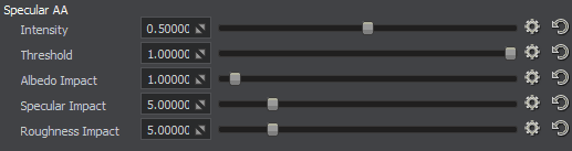
Specular Anti-Aliasing#
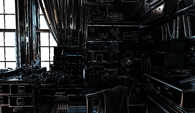
Specular AA enables anti-aliasing of specular highlights. This anti-aliasing is performed by increasing roughness at places where normals change their orientation. Geometry of the model is used, the normal map is not required.
Specular AA Parameters#
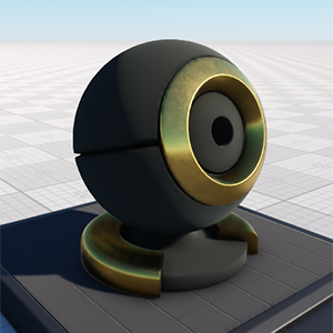
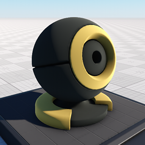
Microfiber Map#
When the Metalness workflow is used, the Microfiber state activates the microfiber texture channel in the shading texture.
When the Specular workflow is used, the Microfiber state activates the microfiber texture.
In the example below, on the first picture, only a part of the mesh is napped according to the microfiber texture. On the second picture, the whole mesh is napped as the microfiber texture doesn't define otherwise.
 |
 |
Microfiber state enabled |
Microfiber state disabled |
Translucent Map#
Translucent map activates an additional translucent texture.
Translucent Texture#
Translucent texture stores information on material's translucency. For example, by using this texture, it is possible to specify parts of the object that aren't translucent (the Translucent parameter won't affect them).
The texture is single-channeled.
In the example below, the following texture is used:
![]()
Translucence is disabled |
Translucent = 1.0, no translucent texture is used |
Translucent = 1.0, translucent texture is set |
The texture can be used, for example, to specify non-translucent areas of vegetation:
Translucence is disabled |
Translucent = 1.0, no translucent texture is used |
Translucent = 1.0, translucent texture is set |
Translucence is disabled |
Translucent = 1.0, no translucent texture is used |
Translucent = 1.0, translucent texture is set |
Displacement#
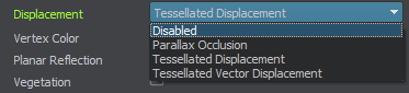
Displacement includes the following options:
Parallax Occlusion Mapping#
Parallax Occlusion enables the parallax effect that provides a convex relief based on a parallax (height) texture.
 |
 |
Disabled Parallax Occlusion |
Enabled Parallax Occlusion |
Available options are:
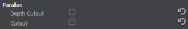
- Depth cutout - apply the depth cutout effect that provides smooth connection of the object with the real mesh. The option enables to make a plane looks like real geometry. Also, the depth cutout effect improves the SSAO calculation on surfaces with parallax maps.
 Disabled Depth cutoutEnabled Depth cutout
 - Cutout - apply the cutout effect that provides smooth edges between the opaque and transparent areas.NoticeThis effect works correctly only when mesh edges match the UV edges.
 Disabled CutoutEnabled Cutout
Parallax Texture#
Parallax map stores information about per-pixel parallax displacement.
The texture uses only R channel:
- White color indicates that the pixels are not displaced.
- Black color indicates that the pixels will be depressed farthest away.
Parallax Parameters#

Parallax Height#
Height is a coefficient to scale the power of the parallax texture displacements. The higher the value, the bigger the normals are.
 |
 |
 |
Height = 0.01 |
Height = 0.03 |
Height = 0.05 |
Min Layers#
Min layers parameter specifies the minimum step of the parallax mapping.
Max Layers#
Max layers parameter specifies the maximum step of the parallax mapping.
Noise#
Noise parameter specifies the size of the noise used for parallax mapping. The higher the value, the less visible the layers.
Cutout UV Transform#
Parallax texture coordinates transformation.
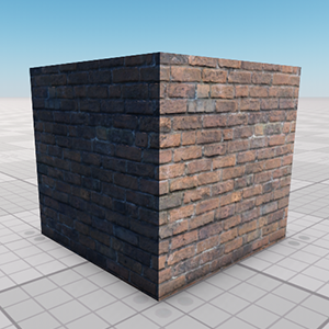
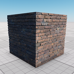
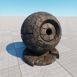
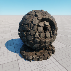
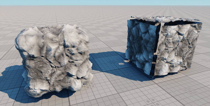
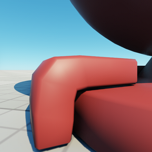
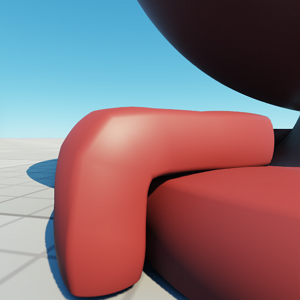
Tessellated Displacement#
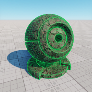
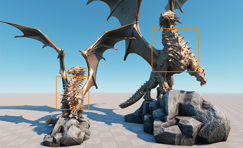
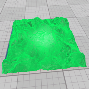
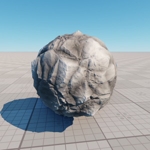
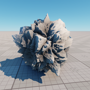
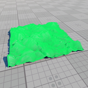
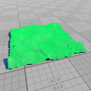
Tessellated Displacement provides a true convex relief by enabling Adaptive Hardware-accelerated Tessellation that subdivides lower-polygon surfaces into finer meshes, which are displaced along the local surface normal based on a Displacement (height) texture.
 |
 |
Disabled Tessellated Displacement |
Enabled Tessellated Displacement |
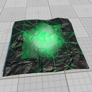
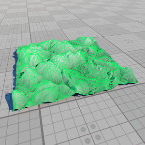
 |
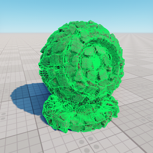 |
Disabled Tessellated Displacement (wireframe) |
Enabled Tessellated Displacement (wireframe) |
Authoring Tips#
Tessellation is intended to add extruded details (spikes and indentations, fine embossed details) rather than drastically change the relief of the coarse mesh. Tessellated Displacement does not affect vertex normals and texture coordinates, so extreme extrusion makes it prone to noticeable visual artifacts, such as texture stretching and inaccurate lighting.
The displacement is applied along the surface normal so tessellated meshes composed of separate parts with hard edges are prone to cracking. To avoid such artifacts, it is recommended to make sure the portions share vertices and edges and have smooth or matching tangents. Another solution would be to create additional polygons that will cover cracked areas from the inside.
Also, displacement applied to polygons from divergent UV shells results in small yet noticeable inconsistency. A decent solution is to paint similar color values on adjacent pixels of divergent UV shells to make sure the Displacement texture doesn't change on junctions.
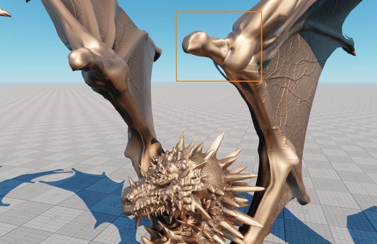
The Displacement effect is bound to the scale of the node, so be careful when dealing with meshes that have different scale but share the same material with Tessellated Displacement enabled. Once combined for optimization purposes, the tessellation scale on such meshes may become significantly different. So such meshes are to be treated separately.
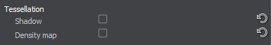
Tessellation Options#
Available options are:
-
Shadow - enable shadow casting from tessellated polygons. This option doubles the number of rendered tessellated polygons, so it is recommended to use it carefully.
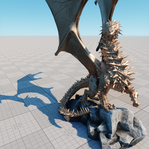
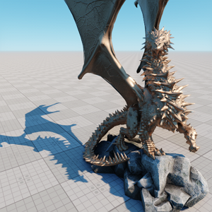 Disabled ShadowEnabled Shadow
 -
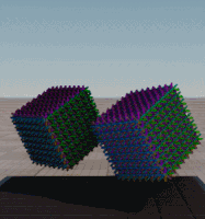
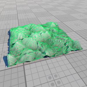
Density Map - enable tessellation density control based on the Tessellation Density Map texture. Lighter pixels of the Density map indicate polygons that should be tessellated more densely. NoticeThe Density Map is sampled at vertices of the control mesh. If the darkened area is too small to cover control mesh vertices, it will not affect the final result.
 Disabled Density MapEnabled Density Map
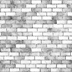
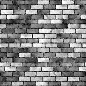
Displacement Texture#
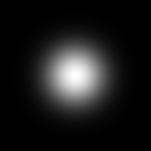
Displacement Texture (height map) stores information about per-pixel Tessellated Displacement.
The texture uses only R channel:
- White color indicates that the pixels will be extruded farthest out.
- Black color indicates that the pixels will be depressed farthest away.
 |
 |
Unnormalized displacement texture |
Normalized displacement texture |
Tessellation Density Map#
Tessellation Density Map stores information about areas that should be tessellated more densely.
The texture uses only R channel:
- White color corresponds to the maximum tessellation density.
- Black color corrseponds to the minimum tessellation density.
Tessellation Displacement Parameters#
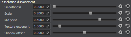
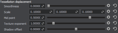
Smoothness#
Smoothness is a coefficient of Phong smoothing of tessellated polygons to get rid of blocky look. Note that normals of vertices are not modified.
 |
 |
Smoothness = 0.0 |
Smoothness = 1.0 |
Scale#
Scale parameter specifies the intensity of displacement in units.
 |
 |
Scale = 0.1 |
Scale = 0.4 |
Mid Point#
Mid Point parameter defines the origin color value of the Displacement texture. For example, the value of 0.5 means that grey pixels will not be affected and lighter and darker pixels will be displaced.
Texture Exponent#
Texture Exponent parameter specifies the gamma of the Displacement texture.
Shadow Offset#
Shadow Offset sets an offset of shadows for fine-tuning.
- Higher values move shadow polygons farther from the light source.
- Lower values move shadow polygons closer to the light source.
Tessellation Density Parameters#
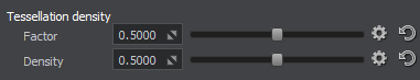
Factor#
Factor is a coefficient of tessellation intensity. The higher the value, the more dense the mesh will be.
 |
 |
Factor = 0.1 |
Factor = 0.5 |
Density#
Density is coefficient for subpixel reduction of polygons. The value of 1 corresponds to the highest mesh density defined by the Factor parameter.
 |
 |
Density = 0.1; Factor = 0.5 |
Density = 1.0; Factor = 0.5 |
Shadow Factor#
Factor is a coefficient of tessellation intensity for shadow polygons. The higher the value, the more dense the mesh will be.
Shadow Density#
Density is coefficient for subpixel reduction of polygons. The value of 1 corresponds to the highest mesh density defined by the Shadow Factor parameter.
Tessellation Distance Falloff Parameters#
The following parameters define the tessellation falloff with the distance for optimization purposes.
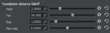
Near#
Near parameter specifies the distance in units from the camera where tessellation falloff starts.
Far#
Far parameter specifies the distance of tessellation falloff. Thus, there will be no tessellation effect at the distance of Near + Far units.
Exp#
Exp parameter determines how fast the tessellation intensity decreases with the distance.
Max Mip#
Max Mip parameter specifies the maximum allowed mipmap level of the Displacement texture to avoid losing tessellation details with the distance.
Tessellation Culling Parameters#
The following group of parameters determines the operation of backface tessellation culling optimization.
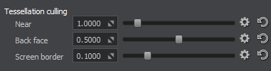
Near#
Near parameter specifies the distance in units from the camera where tessellation culling starts working.
Back Face#
Back Face parameter determines the angle between the camera and a polygon of the control mesh, at which this polygon is not tessellated.
|
|
Back Face = 0.0 |
Back Face = 1.0 |
Screen Border#
Screen Border parameter specifies the screen border offset to prevent undesired culling of tessellated polygons outside the screen.
Shadow Back Face#
Shadow Back Face parameter determines the angle between the camera and a shadow polygon of the control mesh, at which this polygon is not tessellated.
Shadow Screen Border#
Shadow Screen Border parameter specifies the screen border offset to prevent undesired culling of tessellated shadow polygons outside the screen.
Tessellated Vector Displacement#
This type of displacement acts the same way as the Tessellated Displacement except it uses an RGB texture which makes it possible to achieve overhanging polygons.
Along with the common tessellation options, available options are:
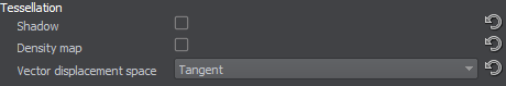
- Vector Displacement Space - the space basis in which the data from the Displacement texture is considered. The following options are available:
- Tangent - tangent space of the surface
- Object - local object transformation
- World - world space
Displacement Texture#
Displacement Texture stores information about per-pixel Tessellated Vector Displacement.
The texture uses RGB channels:
- R channel controls displacement along the X axis.
- G channel controls displacement along the Y axis.
- B channel controls displacement along the Z axis.
Tessellation Vector Displacement Parameters#
Available options correspond to the common tessellation displacement parameters, however, the Scale parameter has a different application:
Scale#
Scale parameter specifies the intensity of displacement in units along the X, Y and Z axes correspondingly.
Calculate Tangent Space#
Calculate tangent space enables calculating the tangent space in the shader. It can be used for materials applied to geometry with incorrect tangents or to geometry without tangents.
Normals Rotated to Camera#
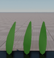
If enabled, Normals Rotated to Camera makes all normals of the surface oriented towards the camera ignoring the geometry normals. This option can be used for vegetation to make the fact that leaves and grass blades are composed of polygons less noticeable.
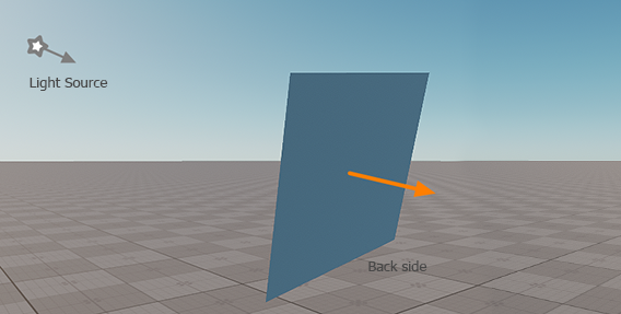
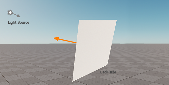
Backside Normal#
Backside Normal enables you to choose the orientation of normals for the back sides of polygons.
Available options are:
- To Back Side - when seen from the back, the polygon is lit normally according to the normal of the back side.
- To Front Side - the back side of the polygon is lit the same way as the front side, creating an effect of a thin translucent material.
Geometry Inflation#
Geometry inflation allows you to apply an additional visual effect without real geometry changing. By using this option, you can create wires and balloons by specifying the type of inflation.
Available options are:
- Disabled - disables geometry inflation.
- Wire - wire type. It will bloat the geometry normals to provide more realistic wire depending on the distance to the mesh.
- Balloon - balloon type. It bloats the geometry by specified constant.
Geometry Inflation Parameters#

Angle Fade#
Angle fade enables cutting out the surfaces that are not perpendicular to the camera view direction vector. This option can be used to gain performance.
The option activates the Angle Power and Angle Offset parameters.
- The option is available for Alpha Test transparent materials only.
- Shadows cast by the surface are not cut out.
Angle Power#
Angle fade power is a coefficient to scale the angle at which the surface is cut out.
The pictures below demonstrate the difference between foliage with disabled and enabled angle fade (Angle Power = 3.0) depending on the angle between the surface normal and the camera view direction vector.
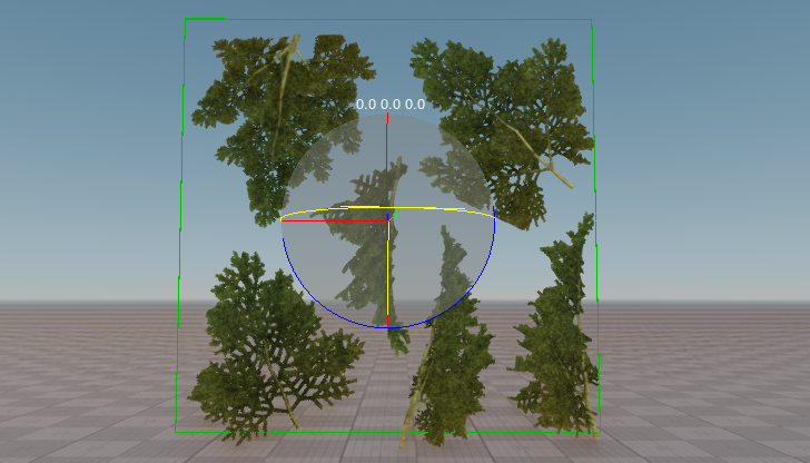

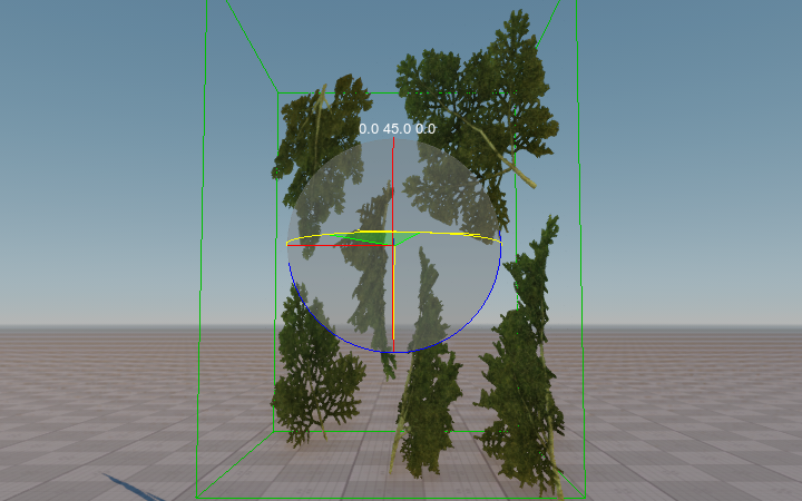

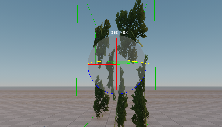
Angle Offset#
Angle fade offset sets an offset for the angle fade power parameter.
Jitter Transparency#
Jitter transparency enables creating deferred transparency by using jittering. The effect is similar to the screen-door transparency, it imitates transparency by means of alpha testing and moving (jittering) of pixels. This state can be used when such result is acceptable and post-effects are applied to the material.
Jitter transparency disabled |
Jitter transparency enabled |
Refraction#
Refraction enables post-processing refraction for the material. You can adjust global refraction settings via the Render -> Postprocess section of the Settings window.
 |
 |
Refraction disabled |
Refraction enabled |
The following group of options becomes available when Refraction is enabled.
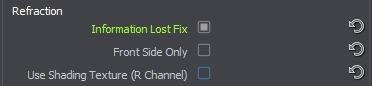
Information Lost Fix#
Enables correction of refractions for "information lost" areas. The source of refraction is the whole screen and not only the internal volume of the object
 |
 |
Information Lost Fix option disabled |
Information Lost Fix option enabled |
Front Side Only#
Enables rendering of refractions only for front faces. This option can be used for glass objects with no cavities inside, or for glass tanks containing some liquid.
 |
 |
Front Side Only option enabled |
Front Side Only option disabled |
Use Shading Texture (R-Channel)#
Enables using the R-channel of the shading texture to modulate the Index of Refraction (IOR) across all surfaces of the object. This option makes it possible to simulate increased refraction for thicker walls of glass objects making it look more realistic.
Refraction Parameters#
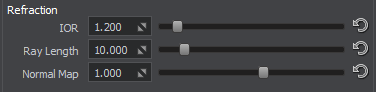
IOR#
IOR sets the Index of Refraction (IOR) for the materal. The higher the value, the more intense the refraction is.
 |
 |
Power = 1.04 |
Power = 1.16 |
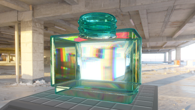
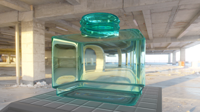
Ray Length#
Ray Length represents length of refracted rays. This parameter is used for visual correction of refractions, depending on the distance from the surface to objects behind it.
 |
 |
 |
Ray length = 1.0 |
Ray length = 2.0 |
Ray length = 5.0 |
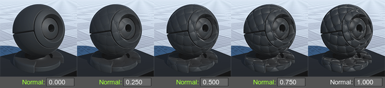
Normal Map#
Normal map is a coefficient to scale the intensity of the normals (provided by a normal map). The higher the value, the higher the normal texture effect is.
 |
 |
 |
Normal map = 0.0 |
Normal map = 1.0 |
Normal map = 2.0 |
Transparent Blur#
Transparent blur enables creating transparent matte objects (e.g. matte glass).
In the example below, the transparency preset is Additive.
![]()
transparent_blur#
transparent_blur sets the degree of blurring.
Transparent blur disabled |
Transparent blur enabled (transparent_blur parameter is set to 0.2) |
Shadows#
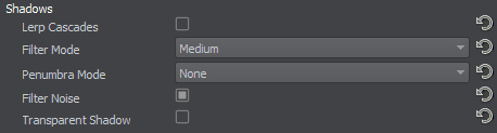
These options control rendering of shadows cast on transparent objects.
This group of settings is available for transparent materials only.
Enabling/disabling shadows options via Rendering -> Shadows menu does not affect transparent materials, as they are controlled per-material via the group of options listed below.
Lerp Cascades#
Lerp Cascades enables linear interpolation for shadows cascades. When enabled, transitions between cascades become smoother. However, the option drops performance, as in the transition parts 2 shadow maps are rendered.
Filter Mode#
Filtering mode to be used for shadows from all light sources cast on the material. This mode determines the quality of soft shadows reducing the stair-step effect. Higher quality produces smoother shadows. Available values:
- Disabled - filtering for shadows is disabled, the stair-step effect is clearly seen at the edges of shadows.
- Low — low quality
- Medium — medium quality
- High — high quality
- Ultra — ultra quality
Penumbra Mode#
Quality mode to be used for rendering penumbra from all light sources cast on the material. This mode enables simulation of real-world shadows by keeping sharp contact shadows closer to the base and softening the farther the shadow stretches away. Higher quality produces softer shadows. Available values:
- Disabled - penumbra rendering is disabled, shadow edges are crisp and sharp (no shadow softness at all).
- Low — low quality
- Medium — medium quality
- High — high quality
- Ultra — ultra quality
Filter Noise#
Toggles the use of noise for shadow filtering on and off. This noise is used for smoothing shadows cast on the material and reducing the stair-step effect at the edges of shadows.
Penumbra Noise#
Toggles the use of noise for penumbra rendering on and off. This noise is used for smoothing soft shadows cast on the material.
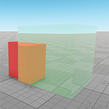
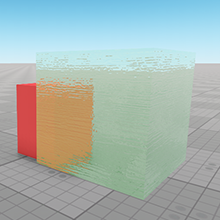
Transparent Shadow#
Transparent shadow enables creating translucent shadows. The state can be used when translucent shadows are required.
In the example below, the transparency preset is Alpha blend and the Alpha value of the Albedo color is set to 70.
![]()
![]()
UV Mapping#
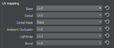
These options specify which UV coordinates of the mesh will be used for textures.
Base Map#
Base option specifies which UV coordinates of the mesh will be used for base textures.
- First UV - map the texture using the first UV coordinates of the mesh.
- Second UV - map the texture using the second UV coordinates of the mesh.
- Triplanar - map the texture using triplanar mapping instead of UV coordinates of the mesh (the texture is rotated with the mesh).
- Triplanar World - map the texture using triplanar mapping instead of UV coordinates of the mesh (the texture is always projected atop).
- Overlap - map the texture using object transformation (the texture is rotated with the mesh).
- Overlap World - map the texture using world transformation (the texture is always projected atop).
Detail Map#
Detail option specifies which UV coordinates of the mesh will be used for detail textures.
- First UV - map the texture using the first UV coordinates of the mesh.
- Second UV - map the texture using the second UV coordinates of the mesh.
- Triplanar - map the texture using triplanar mapping instead of UV coordinates of the mesh (the texture is rotated with the mesh).
- Triplanar World - map the texture using triplanar mapping instead of UV coordinates of the mesh (the texture is always projected atop).
- Overlap - map the texture using object transformation (the texture is rotated with the mesh).
- Overlap World - map the texture using world transformation (the texture is always projected atop).
Detail Mask#
Detail mask option specifies which UV coordinates of the mesh will be used for the detail blend mask texture.
- Base - map the texture using base UV coordinates.
- Detail - map the texture using detail UV coordinates.
- First UV - map the texture using the first UV coordinates of the mesh.
- Second UV - map the texture using the first UV coordinates of the mesh.
- Triplanar - map the texture using triplanar mapping instead of UV coordinates of the mesh (the texture is rotated with the mesh).
- Triplanar World - map the texture using triplanar mapping instead of UV coordinates of the mesh (the texture is always projected atop).
- Overlap - map the texture using object transformation (the texture is rotated with the mesh).
- Overlap World - map the texture using world transformation (the texture is always projected atop).
Ambient Occlusion Map#
Ambient occlusion option specifies which UV coordinates of the mesh will be used for the AO texture.
- Base - map the texture using base UV coordinates.
- First UV - map the texture using the first UV coordinates of the mesh.
- Second UV - map the texture using the second UV coordinates of the mesh.
SSBevel Map#
SSBevel option specifies which UV coordinates of the mesh will be used for the SSBevel map.
- First UV - map the texture using the first UV coordinates of the mesh.
- Second UV - map the texture using the second UV coordinates of the mesh.
- Triplanar - map the texture without using UV coordinates of the mesh (textures are projected by using triplanar mapping).
Post Processing#
Post processing options activate post processing effects for the material.
- SSAO - enables screen space ambient occlusion. Available for opaque and alpha test materials (materials with the Alpha test transparency preset enabled).
- SSR - enables screen space reflections. Available for opaque and alpha test materials (materials with the Alpha test transparency preset enabled).
- SSSSS - enables subsurface scattering. Available for opaque and alpha test materials (materials with the Alpha test transparency preset enabled).
- DOF - enables the depth of field effect. Available for both opaque and transparent materials.
- Motion Blur - enables the motion blur effect. Available for both opaque and transparent materials.
- Screen-Space Shadows - enables screen-space shadows. Available for both opaque and transparent materials.
- Shoreline Wetness - enables the wetness effect for objects near the shoreline. Available for opaque and alpha test materials (materials with the Alpha test transparency preset enabled).
Light Passes#
- Environment and emission - enables rendering of the material illuminated by an environment probe.
- Light omni - enables rendering of the material illuminated by an omni light.
- Light proj - enables rendering of the material illuminated by a projected light..
- Light world - enables rendering of the material illuminated by a world light.
Textures#
All of the textures fields have set default textures, which can be replaced by your own ones. Availability of some textures depends on the set States values.
Metalness Wokflow: Base Textures#

Albedo Texture#
Albedo texture specifies the color of the surface.
|
|
|
Without albedo texture
|
With albedo texture
|
The texture is 4-channeled:
- RGB values store color information.
- An alpha (A) value stores transparency information:
- White color indicates that the area will be visible.
- Black color indicates that the area will be transparent.
Shading Texture#
Shading texture is a container for four different textures:
- The R channel stores a metalness texture.
- The G channel stores a roughness texture.
- The B channel stores a specular texture.
- The A channel stores a microfiber texture.
Metalness Texture#
A metalness texture stores information about material's metalness:
- White pixels indicate that material is metal.
- Black pixels indicate that material is dielectric.
|
|
|
The whole applied texture channel is white
|
The applied texture channel is partially white (reflective areas) and black (non-reflective white splashes)
|
Roughness Texture#
A roughness texture stores information about material's roughness:
- White pixels indicate that material is rough.
- Black pixels indicate that material is smooth.
|

|
|
Without the applied texture channel
|
With the applied texture channel
|
Specular Texture#
A specular texture stores the light reflectance information. It defines shininess and a highlight color of the surface. The lighting is calculated as a Lambertian lighting model plus a surface angle, light angle, and viewing angle dependent specular highlight (Blinn-Phong lighting model).
- White color indicates that the area will be reflective.
- Black color indicates that there will be no reflections.
|
|
|
Without the applied specular texture channel
|
With the applied specular texture channel
|
Microfiber Texture#
A microfiber texture creates an effect of napped surface. The lighter the pixel, the more napped material will be.
 |
 |
Without fibers texture |
With fibers texture |
Normal Map#
Normal map stores information required to achieve an effect of Normal Mapping (a technique creating the illusion of depth for adding details without using additional polygons). When calculating lighting of the surface, the mesh geometry is overridden by the normals value.
|
|
|
Without normal map
|
With normal map
|
The texture is 2-channeled:
- RG values store two components of a surface normal.
- B value is calculated based on the R and G values in run-time.
Specular Wokflow: Base Textures#

Diffuse Texture#
Diffuse texture specified the color of the surface. It is lightened according to a Lambertian lighting model (light intensity is permanent regardless of the camera motion and rotation and depends solely on the angle between the surface and the light direction).
The texture is 4-channeled:
- RGB values store color information.
- An alpha (A) value stores:
- Transparency information (if the Alpha test option is enabled):
- White color indicates that the area will be visible.
- Black color indicates that the area will be transparent.
- Detail mask.
- Transparency information (if the Alpha test option is enabled):
Normal Map#
Normal map stores height information required to achieve an effect of Normal Mapping (a technique creating the illusion of depth for adding details without using more polygons). When calculating lighting of the surface, the mesh geometry is overridden by the normals value.
The texture is 2-channeled:
- RG values store two components of a surface normal.
- B value is calculated based on the R and G values in run-time.
Specular Map#
Specular map stores the light reflectance information. It defines shininess and a highlight color of the surface. The lighting is calculated as a Lambertian lighting model plus a surface angle, light angle, and viewing angle dependent specular highlight (Blinn-Phong lighting model).
The texture is 4-channeled:
- RGB values store reflection color and intensity:
- White color indicates that the area will be reflective.
- Black color indicates that there will be no reflections.
- An alpha (A) value specified the specular power (Gloss):
- White color indicates that the specular highlights are very bright and intense.
- Black color indicates that the specular highlights are dull.
Microfiber Texture#
Microfiber texture creates an effect of napped surface. The lighter the pixel, the more napped material will be.
|
|
|
|
Without microfiber texture
|
With microfiber texture
|
The texture uses only R channel.
Detail Textures#
An additional set of the textures to form a material layer. The set contains all the textures from Base textures group, except for the Microfiber texture.
For the Specular workflow, the mask of the Detail textures set is specified in the Alpha channel (A) of its diffuse texture.
Detail Blend Mask#
Detail blend mask is a mask for two detail textures. Determines the way for two base and detail textures to be rendered.
The texture is 1-channeled:
- R values store information about which textures will be rendered:
- Black areas - base textures will be shown.
- Red areas - detail textures will be shown.
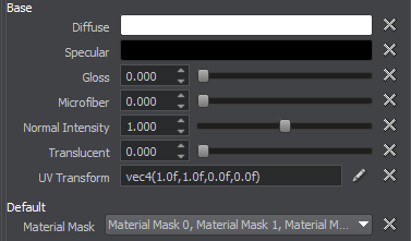
Parameters#
Texture Coordinates Transformation#
![]()
Texture coordinates transformation parameter is an arbitrary expression (script) executed at run time. It is treated as a vector of four float components, consisting of two pairs of vector elements:
- Scale texture coordinates, along the X and Y axes.
For example, by the scale of 2 ;2 the texture will be repeated four times on the surface. See the second picture below.
- An offset of the texture respectively to its initial position along X and Y axes.
For example, by the offset of 0.5 along the X axis the texture will be repositioned to the right (so the left edge of the texture will be rendered in the center). See the third picture below.
|
|
|

|

|

|
Edit Texture Coordinates
Click the Gear icon to open the drop-down menu.
![]()
There are three modes available:
-
Simple mode provides adjustment of the default parameters for texture coordinates transformation.
- Scale X - the first component of the vector defining the scale along the X axis.
- Scale Y - the second component of the vector defining the scale along the Y axis.
- Offset X - the third component of the vector defining the offset along the X axis.
- Offset Y - the fourth component of the vector defining the offset along the Y axis.
-
Animated mode provides the parameters of procedural animation of texture coordinates.
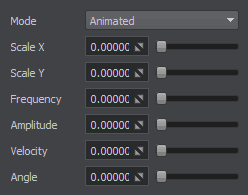
- Scale X - the first component of the vector defining the scale along X axis.
- Scale Y - the second component of the vector defining the scale along Y axis.
- Frequency - the frequency of the circular motion.
- Amplitude - the maximum extent of the circular motion, in pixels.
- Velocity - the velocity of the constant linear offset, in pixels per frame.
- Angle - the direction of the constant linear offset, in degrees.
Expression mode allows using expressions in the parameter field. The type of the expression result must be one of the following:
-
int - an integer number.

The result will be equal to vec4(4.0f, 4.0f, 4.0f, 4.0f)
long - a long integer.

The result will be equal to vec4(2.0f, 2.0f, 2.0f, 2.0f)
float - a floating point value.

The result will be equal to vec4(3.0f, 3.0f, 3.0f, 3.0f)
double - a double value.

The result will be equal to vec4(7.4, 7.4, 7.4, 7.4)
vec3 - a vector of three float components.

The result will be equal to vec4(2.0f, 2.0f, 2.0f, 1.0f)
vec4 - a vector of four float components.

The result will change in Offset Y each frame due to time.
dvec3 - a floating point value.

The result will be equal to vec4(2.0f, 2.0f, 2.0f, 1.0f)
dvec4 - a floating point value.

The result will be equal to vec4(2.0f, 2.0f, 2.0f, 2.0f)
A number of aliases to variables and functions are available from the expression, for convenience:
- ifps - a global variable referring to the engine.game.getIFps() function.
- time - a variable referring to the engine.game.getTime() function.
- noise( float pos, float size, int frequency ) - a function referring to the engine.game.getNoise1() function.
- random( float from, float to ) - a function referring to the engine.game.getRandomFloat() function.
- getNode() - a function returning a current node pointer.
- getParent() - a function returning a parent node pointer.
- getNumChildren() - a function returning the number of children nodes.
- getChild( int num) - a function returning a node child by its number.
- getState( string name ) - a function returning a specified state of the current material.
- getParameter*( string name ) - a function returning the value of a specified parameter of the current material.
-
Material Mask#
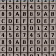
Material mask specifies a material bit mask that is used for projecting the decal. If the material mask of the surface material matches the decal material mask, the decal is projected onto it.
Base Textures Shading Parameters#
Metalness Workflow: Base Textures Shading Parameters#
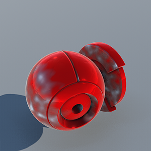
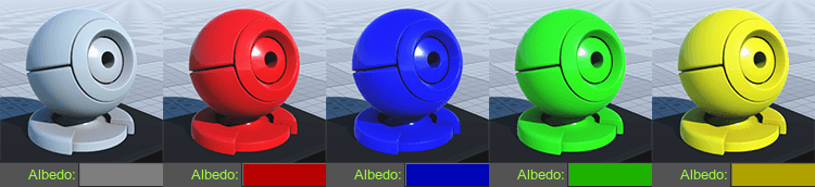
Albedo#
Albedo is a multiplier of the base color of the surface provided by the albedo texture.
Metalness#
Metalness is a multiplier of metalness.
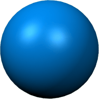
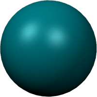
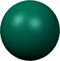
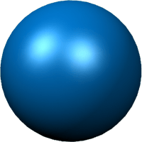
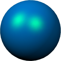
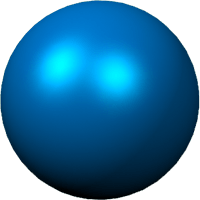
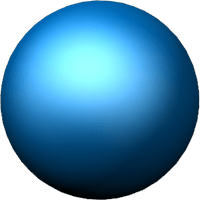
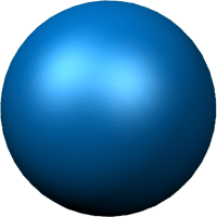
Specular#
Specular is a multiplier for the intensity of highlight provided by the specular texture.
 |
 |
 |
Specular = 0.0 |
Specular = 0.5 |
Specular = 1.0 |
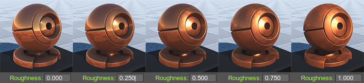
Roughness#
Roughness is a multiplier of the roughness of a surface.
Normal Intensity#
Normal Intensity is an intensity of the relief of the normal map.
Translucent#
Translucent is a scale of the translucency effect, which permits light to pass through the object, but diffuses it so objects on the opposite side are not clearly visible.
Translucent = 0.0 |
Translucent = 0.5 |
Translucent = 1.0 |
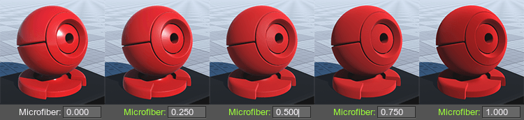
Microfiber#
Microfiber is a coefficient to scale the intensity of the microfiber (provided by a microfiber texture). The higher the value, the higher the microfiber texture effect is.
Transparent Multiplier#
Transparent multiplier is a multiplier of material's transparency. The higher the value, the less transparent the material.
Transparent multiplier = 0.7; Transparent pow = 1.0 |
Transparent multiplier = 1.0; Transparent pow = 1.0 |
Transparent multiplier = 1.3; Transparent pow = 1.0 |
Transparent Pow#
Transparent pow is a power of material's transparency. The higher the value the more transparent the material.
Transparent pow = 0.5; Transparent multiplier = 1.0 |
Transparent pow = 1.0; Transparent multiplier = 1.0 |
Transparent pow = 1.5; Transparent multiplier = 1.0 |
UV Transform#
Base textures coordinates transformation.
Triplanar Blend#
Specular Worklow: Base Textures Shading Parameters#
Diffuse#
Diffuse defines the base color of the surface.
|
|
|

|

|

|
Specular#
Specular is a color picker to choose the auxiliary specular color for the specular texture. It can be used for specifying different specular colors for one texture or modifying the texture color on the spot. The specular color of the texture and this color will be blended.
|
|
|

|

|

|
Gloss#
Gloss is a coefficient modifying the size of the highlight (Phong shading). Low values imitate wider highlights, typically appropriate to create diffuse reflection from mat surfaces. High values imitate pinpoint highlights, typically appropriate to create uniform reflection of light rays from glossy surfaces.
|
|
|

|

|

|
Microfiber#
Microfiber is a coefficient to scale the intensity of the microfiber (provided by a microfiber texture). The higher the value, the higher the microfiber texture effect is.
Normal Intensity#
Normal intensity is a coefficient to scale the intensity of the normals (provided by a normal map). The higher the value, the higher the normal texture effect is.
Translucent#
Translucent is a scale of the translucency effect, which permits light to pass through the object, but diffuses it so objects on the opposite side are not clearly visible.
Translucent = 0.0 |
Translucent = 0.5 |
Translucent = 1.0 |
Transparent Multiplier#
Transparent multiplier is a multiplier of material's transparency. The higher the value, the less transparent the material.
Transparent multiplier = 0.7; Transparent pow = 1.0 |
Transparent multiplier = 1.0; Transparent pow = 1.0 |
Transparent multiplier = 1.3; Transparent pow = 1.0 |
Transparent Pow#
Transparent pow is a power of material's transparency. The higher the value the more transparent the material.
Transparent pow = 0.5; Transparent multiplier = 1.0 |
Transparent pow = 1.0; Transparent multiplier = 1.0 |
Transparent pow = 1.5; Transparent multiplier = 1.0 |
UV Transform#
Base textures coordinates transformation.
Triplanar Blend#
Detail Textures Shading Parameters#
Metalness Workflow: Detail Textures Shading Parameters#
A set of the shading parameters for detail textures:
Albedo#
Albedo is a multiplier of the detail color of the surface provided by the detail albedo texture similar to the base texture Albedo parameter.
Metalness#
Metalness is a multiplier of metalness provided by the detail metalness texture similar to the base texture Metalness parameter.
Roughness#
Roughness is a multiplier of the roughness of a surface similar to the base texture Roughness parameter.
Microfiber#
Microfiber is a coefficient to scale the intensity of the microfiber (provided by a microfiber texture) similar to the base texture Microfiber parameter. The higher the value, the higher the microfiber texture effect is.
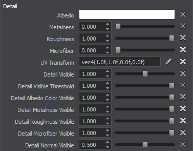
UV Transform#
Detail textures coordinates transformation.
Triplanar Blend#
Visibility#
Visibility specifies a multiplier of visibility of the detail texture.
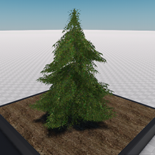
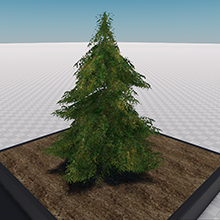
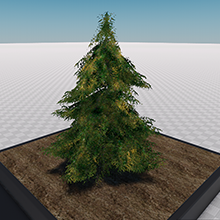
In the example below, Angle fade is set to Object transform.
 |
 |
 |
Visibility = 0.5; Visibility threshold = 1.0 |
Visibility = 1.0; Visibility threshold = 1.0 |
Visibility = 2.0; Visibility threshold = 1.0 |
Visibility Threshold#
Visibility threshold influences to sharpness of the smooth transitions between the base and detail textures.
In the example below, Angle fade is set to Object transform.
 |
 |
 |
Visibility threshold = 0.0; Visibility = 1.0 |
Visibility threshold = 0.5; Visibility = 1.0 |
Visibility threshold = 1.0; Visibility = 1.0 |
Albedo Visibility#
Albedo visibility specifies the influence of the detail texture albedo over the base texture albedo.
In the example below, Detail blending is set to Overlay, the base albedo texture is yellow and the detail albedo texture is red.
 |
 |
 |
Albedo visibility = 0.0 |
Albedo visibility = 0.5 |
Albedo visibility = 1.0 |
Metalness Visibility#
Metalness visibility specifies the influence of the detail texture metalness over the base texture metalness.
In the example below, Detail blending is set to Overlay, the base texture metalness is set to 0.7 and the detail texture metalness is 0.1. So, increasing the metalness visibility leads decreasing the resulting metalness of the material.
 |
 |
 |
Metalness visibility = 0.0 |
Metalness visibility = 0.5 |
Metalness visibility = 1.0 |
Roughness Visibility#
Roughness visibility specifies the influence of the detail texture roughness over the base texture roughness.
In the example below, Detail blending is set to Overlay, the base texture roughness is 0.5 and the detail texture roughness is 1.0. So, increasing the roughness visibility leads increasing the resulting roughness of the material.
 |
 |
 |
Roughness visibility = 0.0 |
Roughness visibility = 0.5 |
Roughness visibility = 1.0 |
Microfiber Visibility#
Microfiber visibility parameter specifies the influence of the detail texture microfiber over the surface.
In the example below, Detail blending is set to Overlay, the base texture microfiber is 1.0 and the detail texture microfiber is 0.0. So, increasing the microfiber visibility leads decreasing the microfiber effect for the material.
 |
 |
 |
Microfiber visibility = 0.0 |
Microfiber visibility = 0.5 |
Microfiber visibility = 1.0 |
Specular Visibility#
Specular visibility parameter specifies the influence of the detail texture specular over the surface.
Normal Visibility#
Normal visibility parameter specifies the influence of the detail texture normal over the surface.
In the example below, Detail blending is set to Overlay.
 |
 |
 |
Normal visibility = 0.0 |
Normal visibility = 0.5 |
Normal visibility = 1.0 |
Detail Mask Parameters#
- UV Transform is detail mask texture coordinates transformation.
- Triplanar blend
NoticeThe parameter is available when the Triplanar mapping is used to project the texture.
Detail Angle Fade Parameters#

- Fade is a coefficient to scale the angle at which detail texture fades.
- Threshold influences to sharpness of the smooth transitions between the base texture and the detail texture for which the Angle fade option is enabled.
Specular Workflow: Detail Textures Shading Parameters#
A set of the shading parameters for detail textures:
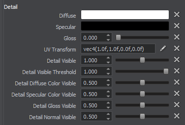
Diffuse#
Diffuse is a multiplier of the detail color of the surface provided by the detail diffuse texture similar to the base texture Diffuse parameter.
Specular#
Specular is a color picker to choose the auxiliary specular color for the detail specular texture similar to the base texture Specular parameter.
Gloss Scale#
Gloss is a parameter modifying the size of the highlight of the detail texture similar to the base texture Gloss parameter.
UV Transform#
Detail textures coordinates transformation.
Triplanar Blend#
Visibility#
Visibility specifies a multiplier of visibility of the detail texture.
In the example below, Angle fade is set to Object transform.
 |
 |
 |
Visibility = 0.5; Visibility threshold = 1.0 |
Visibility = 1.0; Visibility threshold = 1.0 |
Visibility = 2.0; Visibility threshold = 1.0 |
Visibility Threshold#
Visibility threshold influences to sharpness of the smooth transitions between the base and detail textures.
In the example below, Angle fade is set to Object transform.
 |
 |
 |
Visibility threshold = 0.0; Visibility = 1.0 |
Visibility threshold = 0.5; Visibility = 1.0 |
Visibility threshold = 1.0; Visibility = 1.0 |
Diffuse Visibility#
Diffuse visibility specifies the influence of the detail texture diffuse over the base texture diffuse.
In the example below, Detail blending is set to Overlay, the base diffuse texture is yellow and the detail diffuse texture is red.
 |
 |
 |
Diffuse visibility = 0.0 |
Diffuse visibility = 0.5 |
Diffuse visibility = 1.0 |
Specular Visibility#
Specular visibility specifies the influence of the detail texture specular over the base texture specular.
Gloss Visibility#
Gloss visibility specifies the influence of the detail texture gloss over the base texture gloss.
In the example below, Detail blending is set to Overlay, the base texture gloss is 0.5 and the detail texture gloss is 1.0. So, increasig the gloss visibility leads increasing the resulting gloss of the material.
 |
 |
 |
Gloss visibility = 0.0 |
Gloss visibility = 0.5 |
Gloss visibility = 1.0 |
Normal Visibility#
Normal visibility parameter specifies the influence of the detail normal texture normal over the surface.
In the example below, Detail blending is set to Overlay.
 |
 |
 |
Normal visibility = 0.1 |
Normal visibility = 0.6 |
Normal visibility = 0.9 |
Detail Mask Parameters#
- UV Transform is detail mask texture coordinates transformation.
- Triplanar blend
NoticeThe parameter is available when the Triplanar mapping is used to project the texture.
Detail Angle Fade Parameters#
- Fade is a coefficient to scale the angle at which detail texture fades.
- Threshold influences to sharpness of the smooth transitions between the base texture and the detail texture for which the Angle fade option is enabled.
The information on this page is valid for UNIGINE 2.20 SDK.