Bit Masking
Bit masking is a flexible mechanism used to access only the specific bits in a set of data. It can be applied to the following systems:
- Rendering into viewport
- Shadowing
- Reflections rendering
- Collisions
- Intersections
- Decals
- Fields
- Sound sources
- Physicals
- Pathfinding
To specify the mask, click the corresponding mask button (Viewport, Shadow, Intersection, etc.) and enable required bits of a 32-bit mask. Enabling a bit means setting the value of 1 (when disabled, the value is 0). The resulting mask is displayed as hexadecimal characters on the top of the context menu window. The name of selected bit or bits is displayed on the mask button.
To collapse the context menu, click the mask button once again.
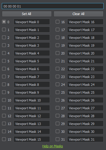
Bit mask with the first bit turned on
|
|
Default names of bits can be changed. The name entered in a field is assigned to a selected bit in all masks of this type. For example, if you assign a name to the first bit of the Viewport mask of a surface, the same name is displayed for the first bit of the Camera's Viewport mask. Bit masks names are assigned locally and stored in the <Project Name>/data/default.bitmasks file, which is created when you open your project in UnigineEditor for the first time.
Comparing Masks#
Masks are compared bitwise using binary operator and. As a result, the first bit of the first mask is compared to the first bit of the second mask, the second bit — to the second one, and so on.
For example, the following viewport masks have 4 matching bits, so they match:
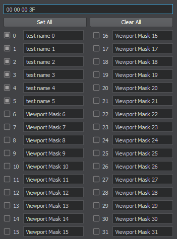 |
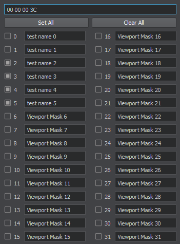 |
The camera Viewport mask with the first 6 bits enabled |
The object's Viewport mask with the second, third, fourth, and fifth bits enabled |
Each mask has a hexadecimal representation, which is displayed in the input field of the context menu. You can copy the hexadecimal value of one mask and paste it in the input field of another mask to enable the same bits of the mask.
See a part of our video tutorial on bit masking dedicated to a more detailed and visualized explanation of the bit masking concept.
Rendering into Viewport#
Objects (along with decals and lights) can be selectively rendered into viewport. To that end, the camera Viewport mask (set in the Camera Settings window opened via the Camera panel), should match the following masks:
- Object surface Viewport mask (Parameters window → Node tab → Surfaces section → Rendering field)
- Object material viewport mask to render the object's material (Parameters window → Node tab → Surface Material section → Common tab → Options field)
Usage Example#
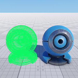
Suppose, we have two objects with the same material. To make one of them to be rendered into viewport and the other one — not to be rendered, we should change the Viewport mask of the second object.

|
|

In the surface Viewport masks of both objects, the same bit Viewport Mask 0 is enabled (00000001)
|

For the first object, all bits of the surface Viewport mask are disabled (the mask is set to 00000000)
|
See the demonstration of how to set rendering into viewport and one more usage example in our video tutorial on bit masking.
Reflection Mask#
The reflection mask (Reflection Viewport) controls rendering of the environment probe reflections and planar dynamic reflections into the viewport of the reflection camera.
The reflection mask can be set:
- For environment probes (Parameters window → Node tab → Baking Settings section → Reflection Viewport Mask button). The mask is used only in combination with dynamic reflections enabled for the environment probe.
- For planar reflections (Parameters window → Node tab → Surface Material section → Parameters tab → Planar Reflection section → Viewport Mask button).
For the dynamic reflection to be rendered, the Reflection Viewport mask of the reflecting material (Parameters window → Node tab → Surface Material section → Parameters tab → Planar Reflection section → Viewport Mask button) must have at least one matching bit with each of the following masks:
- Reflection Viewport mask of the camera (Camera Settings window → Masks field)
- Viewport mask of the object (Parameters window → Node tab → Surfaces section → Rendering field)
- Viewport mask of the object's material (Parameters window → Node tab → Surface Material section → Common tab → Options field)
See also the fragments of our video tutorial on bit masking demonstrating the use of bit masks with baked reflections and dynamic reflections.
Usage Example#
Suppose, you have a reflecting surface and two objects reflected in this surface.
- To render an object without a reflection, either its Viewport mask or its material's Viewport mask should have no matching bits with the planar reflection's Viewport mask or the camera's reflection Viewport mask.
- To render a reflection without an object, the object's Viewport mask or its material's Viewport mask should have no matching bits with the camera's Viewport mask.
In the example below, masks are given in the binary representation. For convenience, let's assume that objects and their materials have identical Viewport masks. For masks to match, they should share 1 in the appropriate bit position. You can convert these masks to the hexadecimal number representation and set the obtained values via UnigineEditor.
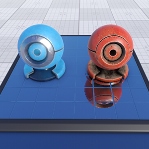
An object without the reflection
|
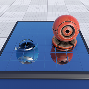
A reflection without the object
|
||||||||||||||||||||||||
|
|
In the first example, the object's Viewport mask doesn't match the camera's reflection Viewport mask. However, it matches the camera's Viewport mask, so the object is rendered.
In the second example, the object's Viewport mask doesn't match the camera's Viewport mask. However, it matches the camera's Reflection Viewport mask and the planar reflection's Viewport mask, so the reflection is rendered.
Shadow Mask#
The Shadow mask controls rendering of a shadow cast by an object lit by a light source.
For a shadow to be rendered, the Shadow mask of the light source that illuminates the object must match the following masks (one bit at least):
- Object surface Shadow mask (Parameters window → Node tab → Surfaces section → Rendering field)
- Object material Shadow mask (Parameters window → Node tab → Surface Material section → Common tab → Options field)
Usage Example#
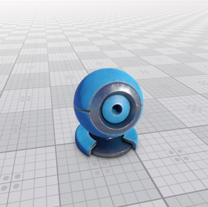
The example below demonstrates the difference. On the left, the Shadow masks of the surface and its material have all bits enabled, thus they have one bit matching the Shadow mask of the light source, and the shadow is rendered. On the right, the Shadow masks of the surface and its material don't match the Shadow mask of the light source, so the shadow isn't rendered.
 |
 |
 Shadow mask of the surface and its material
|
 Shadow mask of the surface and its material
|
 Shadow mask of the light source
|
 Shadow mask of the light source
|
See one more usage example in our video tutorial on bit masking.
Material Mask#
A Material mask is a 24-bit mask that specifies objects onto which the decal can be projected. An object or one of its surfaces can receive the decal only if the object's Material mask corresponds to the Material mask of the decal.
The Material mask can be specified for a selected material on the Parameters tab of the material editor:
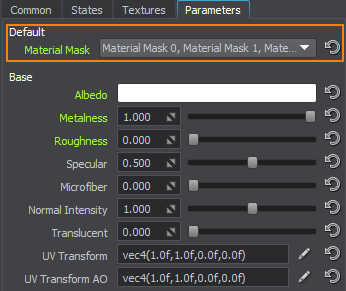
See how the decal projection area can be restricted using the Material mask in our video tutorial on bit masking.
Intersection Mask#
The Intersection mask specifies objects (including objects, nodes, shapes, collision objects, and obstacles) for which intersections will or won't be found. An intersection is found only if the Intersection mask of the object matches the Intersection mask passed as a function argument, otherwise it is ignored.
The mask for the object's surface can be specified via UnigineEditor or API.
The Intersection mask can be used to clarify the object search or increase performance by limiting the number of objects that can participate in intersections.
Our video tutorial on bit masking features two use cases of the Intersection mask: excluding objects from intersection detection and cutting out grass.
Collision Mask#
The Collision mask allows you to filter particular shapes and bodies for physical interaction: only objects with the matching Collision mask will collide. If masks do not match, shapes and bodies simply ignore each other by going through.
For example, we have four bodies that should collide in the following way:
| Body A | Body B | Body C | Body D | |
| Body A |

|
|||
| Body B |

|

|
||
| Body C |

|

|
||
| Body D |

|

|

|
For that, each colliding body should share 1 in the appropriate bit position:
| Body | Mask |
|---|---|
| Body A | 0001 |
| Body B | 0010 |
| Body C | 0110 |
| Body D | 1111 |
See how the Collision mask works in our video tutorial on bit masking.
Exclusion Mask#
An analogue of the Collision mask but working vice versa. It is used to prevent collisions of the shape with other shapes. For shapes with matching Collision masks not to collide, at least one bit of their Exclusion mask should match. 0 enables collisions with all shapes with matching Collision masks. This mask is independent of the Collision mask.
See how the Exclusion mask works in our video tutorial on bit masking.
Physics Intersection Mask#
Physics intersections (between physical objects with bodies and collider shapes, or ray intersections with collider geometry) use a separate mask, other than the one described above and used for world intersections (i.e., between object bound volumes, or ray intersections with object surfaces). This offers more flexibility enabling you to control them independently.
Physics intersections can be used, for example, to detect collisions of spawned particles with physical shapes and bodies, or static collider surfaces to ensure proper interaction, or as a quick way to detect collisions for raycast-wheels of a simulated ground vehicle, or to check if a destructible object or a player was hit by a projectile.
The Physics Intersection mask can be specified via the UnigineEditor or via API for a particle system, a shape, a fracture body, a player actor, or a wheel joint to enable selective physics intersection detection or increase performance by limiting the number of objects that can participate in physics intersections. It san also be set for the object's surface (if this object has no body or shape assigned and is to be treated as a static collider) via UnigineEditor or API.
Physical Mask#
A bit mask that filters objects interacting with physical nodes: force, wind, water. This mask is set according to the same principle as the collision mask. For example, a body with a mismatching mask placed in the physical water will not float.
An example of the Physical mask working with physical effects is shown in our video tutorial on bit masking.
Sound Sources Masks#
Masks can be set via both UnigineEditor and API.
To see and hear how sound-related masks are used, watch our video tutorial on bit masking.
Source Mask#
A bit mask that determines to what sound channels the sound source belongs to. For a sound source to be heard, its mask should match the player's sound mask in at least one bit.
Reverb Mask#
A bit mask that determines which reverberation zones can be heard. For sound to reverberate, at least one bit of this mask should match the player's reverberation mask. At the same time, the Reverb mask of the player should match the Reverb mask of the sound source (but not necessarily in the same bits).
Occlusion Mask#
A bit mask that determines which sound sources are occluded by the selected surface. For a sound source to be occluded by the surface, at least one bit of this mask should match the Occlusion mask of the sound source.
Navigation Mask#
The Navigation mask is used to specify navigation areas that participate or don't participate in pathfinding. The Navigation mask should match the Navigation mask of the route that is calculated within the navigation area; otherwise, the area does not participate in pathfinding.
The Navigation mask for the navigation areas can be specified via:
- UnigineEditor in the Navigation Sector/Navigation Mesh section of the Parameters window
- Unigine API
Using the Navigation mask, you can limit the number of navigation areas, inside which the specific route can be calculated. For example, you can use the mask to calculate 2 non-intersecting routes inside the intersecting navigation areas.
A usage example of the Navigation mask is provided in our video tutorial on bit masking.
Obstacle Mask#
The Obstacle mask is used to specify obstacles inside navigation areas that are or aren't bypassed during pathfinding. The Obstacle mask of an obstacle should match the Obstacle mask of the route that is calculated; otherwise, the obstacle is not taken into account.
Similar to the navigation mask, the obstacle mask can be specified via:
- UnigineEditor in the Obstacle Box/Sphere/Capsule section of the Parameters window
- Unigine API
A usage example of the Obstacle mask is provided in our video tutorial on bit masking.
Field Mask#
The Field mask specifies an area of the field to be applied to grass, water, or clouds. The Field mask of a field node should match the Field mask of the grass, water, or cloud layer .
The Field mask can be set via UnigineEditor or API.
A usage example of the Field mask is provided in our video tutorial on bit masking.