Sound Source
Emulating a real-life sound, it should be considered that all sounds are emitted from a specific source, travel through some space, and then are perceived by the listener. Here a lot of factors come into a play, such as properties of the propagation medium (such as air or water), properties of the sound itself, and geometry of the space. But in the first place, the resulting sound depends on relative positions of sound sources and the listener. Spatialization determines filtering of high frequencies for the left or right channels when the listener is turned to the corresponding side. If the sound is heard from behind, it becomes muffled using the same principle. Therefore, it is of key importance to correctly place sound sources in the scene and orient the listener, if necessary.
UNIGINE enables the same general functionality for the sound sources as for other nodes: they can be easily moved, rotated, or scaled. Besides that, the following specific characteristics can be edited.
Creating a Sound Source#
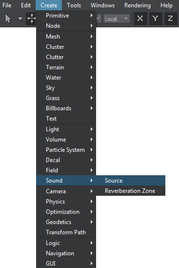
To create a sound source via UnigineEditor:
In the Menu bar, click Create -> Sound -> Source.

- Place the sound source somewhere in the world.
Pitch#
Pitch is a basic parameter corresponding to the frequency of a sound wave. A sound wave, like any other wave, is introduced into a medium by a vibrating object. The frequency of a wave refers to how often particles of the medium vibrate when a wave passes through it. The faster the vibration, the higher the pitch is.
The pitch of a sample can be changed by shifting the frequency of the sound.
- The initial value 1 means there is no shift applied and the sound pitch remains unchanged.
- Each reduction by 50 percent means that the pitch is shifted one octave down (drop of 12 semitones).
- Each doubling means that the pitch is shifted one octave up (12 semitones increase).
Gain#
Another distinct characteristic of the perceived sound is its loudness. Gain is a scalar multiplier for the sound amplitude (height of the wave) determining if the sound should be attenuated.
- By default the gain equals 1, which means that the sound is not attenuated and preserves its original amplitude.
- Setting the gain to 0.5 will result in attenuation of 6 dB.
- Zero value mutes the sound source completely.
Oriented Cone#
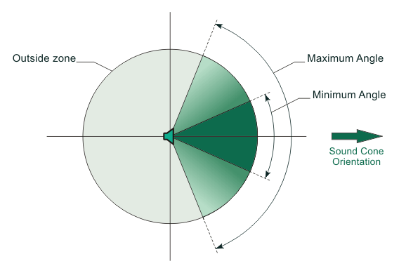
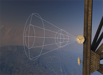
A sound with no orientation has the same amplitude at a given distance in all directions. But it can be focused to a narrow beam and emitted only in one specified direction. To visualize this directional spread of a sound wave, the oriented cone is used. The vertex of the cone is the source itself. The direction of the oriented cone is changed by rotating the node. The inner and outer angles divide the area of sound coverage into the following zones:
- The inner cone is defined by the minimum angle. If the angle equals 360 degrees, the sound source is omnidirectional. When inside the inner cone, the listener perceives the direct sound. It means that its loudness is specified by gain and no additional attenuation besides the distance-related one is applied.
- The outer cone is defined by the maximum angle. If set to 360 degrees, the outer angle covers the entire world. if the inner angle is also 360, the zone for angle-dependent attenuation equivalent to the directional sound is zero. The gain in the outer cone is linearly extrapolated between the general gain and outside the cone gain values. It enables imitating smooth and gradual attenuation of sound.
- The outside zone is the remaining sphere volume that is not included in the oriented cone. The sphere itself is limited to the maximum distance. The sound can still be heard outside the cone, but its attenuation must be different, meaning a separate gain value should be set.

Outer Gain#
Outer Gain is the factor by which the general Gain value is multiplied to determine the effective gain in the outside zone. Note that while changing the general gain result in sound attenuation in all zones and directions, the outer gain affects only the outside zone. By default the outer gain value equals 0 and the sound coverage is limited to the oriented cone.
Outer Gain HF#
Outer Gain HF enhances the source's directivity by filtering high frequencies in the zone outside the cone (in the rear of the source). The underlying reason of this parameter is that sounds in the real world are more directive at high frequencies than at low ones.
- The default 1.0 means that no additional filtering of high frequencies is applied.
- At the minimum setting of 0.0, high frequencies are attenuated by 100 dB more than the low frequencies.
This parameter simulates the directivity of high-frequency attenuation for both the direct emitted and the reverberation sounds.
Minimum and Maximum Distance#
 The amplitude of the sound decreases with the distance. As the listener moves away from the source, at some point it becomes completely out of the hearing range. This point corresponds to the maximum distance. If the maximum distance is set to infinity, it prevents the sound source from becoming inaudible regardless of the listener's position in the virtual world.
On the other hand, approaching the source results in the sound getting louder: the volume doubles when the distance is halved. However, at some point the sound gets as clear, as it should be, and coming closer to the source does not increase the volume any more. This point past which the source is unattenuated is equivalent to the minimum distance.
The minimum and maximum distances are very useful for compensating for the difference in absolute volume levels of the sounds. For example, the sounds of a jet plane and a bee are recorded with approximately the same absolute volume, though being of different intensity in the real life. If the minimum distance for the plane is set to 100 units and for the bee — to 0.2 units (if the scale is congruent to meters), the sounds is perceived as balanced in proportions.
Doppler Effect#
The Doppler effect is a shift of the sound wave frequency (pitch change) depending on the velocities of the source and listener relative to the medium, and the propagation speed of the sound in that medium. The received frequency is higher when compared to the emitted one if the source is approaching the listener, identical at the moment of passing by, and lower during moving off. The Doppler effect is applied to sound sources automatically.
Room Rolloff#
When a sound source is positioned in the reverberating environment, sometimes it is necessary to gain a proper reverberation modulation for the selected sound source. The following reverb-related parameter can be fine-tuned: Room Rolloff. It defines attenuation of the reverberation sound over distance. It is absolutely concurrent with the appropriate parameter of reverberation zone, except being limited to the only source.
Air Absorption#
Air absorption controls the filtering of high frequencies of the emitted sound caused by the propagation medium. With the help of this parameter, atmospheric conditions for the source can be altered when comparing to the environment. Increasing air absorption can imitate the sound coming from a cloud of fog or smoke (more humid atmosphere). Air absorption is a multiplier for the fixed value of 0.994 (-0.05 dB) per unit which represents normal atmospheric humidity and temperature. The parameter value can be set between 0 and 10 giving a range of 0 to 50 dB of attenuation at the reference high frequency per unit.
- By default, the air absorption is set to 0 and high frequency attenuation is disabled.
- If the parameter value is set to 1.0, high frequency attenuation of the emitted sound is applied at a rate of 0.05 dB per unit.
Sound Occlusion#
Simulating sound occlusion is substantial for true-to-life auditory experience. Moving through the world, the listener can get into a place from where the sound source is not seen directly. Imagine a source located behind the wall: it would still modulate the listener's adjacent sound environment, though naturally being not so clearly heard. Any sounds passing from the source to the listener must pass through the wall muffling these sounds and serving as a filter. The sound wave from the source (along with accompanying reflections and reverberation) is modified after hitting the wall and passing through it to the other side. High frequencies are usually removed, leaving a very muffled result. Besides the mentioned physical effect, this occluded sound wave also adds to the reflected sound in the listener's environment.
Occlusion can be enabled and disabled for each sound source individually, selective occlusion adjustment is performed using the Occlusion bit mask that determines which sound sources are occluded by each particular surface of scene objects. Each surface also has an Occlusion coefficient that determines how much it affects sounds in case of occlusion:
- 0.0 — no occlusion, sound volume stays the same in case of occlusion by the surface.
- 1.0 — maximum occlusion, sound is not heard at all in case of occlusion by the surface.
Playback#
The following standard options for the sample sound playback are available: Play, Stop. The playing can also be looped by checking the appropriate box.
See also#
- The SoundSource class to manage sound sources via API