Generating Spline Objects
Spline object (WorldSplineGraph) represents a basic static mesh, tiled or extruded along the segments of a Bezier spline graph, built on the basis of vector data available. As an example of spline object generation let us consider generation of a road network. The basic workflow is as follows:
1. Preparing a Basic Mesh#
First, we create a MeshStatic object, that will be used as a building block for generation of roads.
-
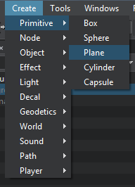
Create a mesh (we use a plane for the road): on the Menu Bar, click Create -> Primitive -> Plane.
-
Specify mesh parameters, for our road we set the following.
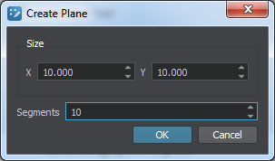 NoticeIt is recommended to use more than a single segment to make road curves smoother.
 -
Move the mesh to the origin.
-
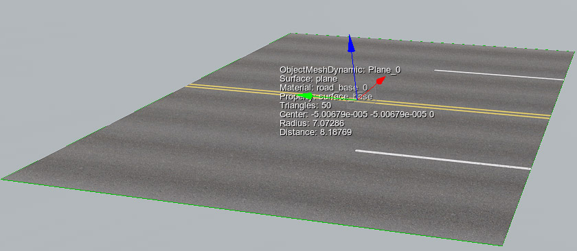
Inherit a material from the mesh_base, set all necessary textures and parameters and assign it to the mesh.
-
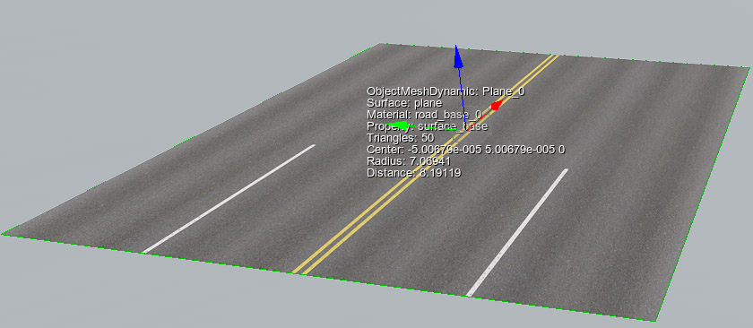
As it was mentioned spline objects are generated by means of extrusion or tiling of the basic mesh along one of the axes X, Y or Z (forward axis). Make sure that your mesh is oriented properly - in this case the forward axis is X (red arrow).
-
Geometry is very resource consuming. Thus, to maintain acceptable performance you should set up LODs for the basic mesh. For each surface of the mesh specify visibility and fade distances. These settings will be used for managing LODs of generated spline objects.
For more information on LOD settings see Setting Up Object LODs.
-
Export your node to a .mesh file and then delete the node.
-
Create a MeshStatic object using the mesh and material you prepared. Move the mesh to the origin and export it to a .node file (e.g. road.node) by clicking the following button in the Nodes window.
-
Now our basic mesh for roads (road.node) is ready to use and you can delete it from the scene.
2. Adding a Vector Data Source and Specifying Tags#
Now, we add a vector data source to be used for generation.
-
Open the Landscape Tool window, for this purpose on the Menu Bar, click Windows -> Landscape.
-
In the Sources panel, specify necessary vector data sources (see Specifying Data Sources section).
NoticeCurrently only *.shp files are supported. -
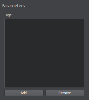
Select each vector data source from the ones you added in the Sources panel and specify parameters in the Parameters panel.
-
Add tags for each type of spline objects you are going to generate by clicking Add and specifying a tag name.
-
For each tag you can specify a set of filters (AND) to select certain data from the vector source. You can add as many filters as necessary. This can be done by selecting attributes from the list and specifying necessary values for each attribute. You can specify as many filters as you need.
NoticeUse "+" (plus) button to add a filter, or "-" (minus) to remove one.
If no filters are specified, all the data from the vector source will be used for generation.

-
Now all necessary tags and filters are added and you can proceed to the next step.
3. Specifying Parameters of Spline Objects#
Now, we must specify basic objects created at the first step and bind them to the tags.
-
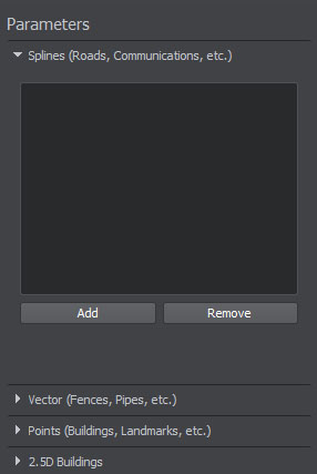
On the Sources panel, select the Vector data source type and the following settings will be displayed in the Spline tab of the Parameters panel.
-
Add a basic mesh object for generation by clicking Add button on the Parameters panel and specify object's name. You can add as many objects as nesessary.
-
For each basic object specify the following parameters:
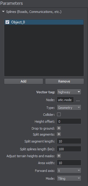
Vector tag The tag to be used for the selected basic object from the list of the tags specified at the second step. Node The path to the basic mesh object's *.node file. Type Type of objects to be generated. One of the following: - Geometry - a static mesh will be generated. Static meshes may require additional alignment with terrain surface, they are costly in terms of performance, but they offer collision detection. This option can be used for example to generate a railway track for the train simulator.
- Decal - a mesh decal will be generated. Decals do not have problems associated with alignment with the terrain surface, as they are projected onto it. They are also performance friendly, but collision detection for decals is not available. This option can be used for example to generate roads for a flight simulator.
- Both - both a static mesh and a mesh decal will be generated. This option can be used to generate static meshes that will be visible within a close distance range (according to LOD settings of the basic mesh) and decals for a long-distance range.
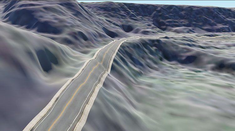
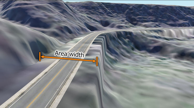
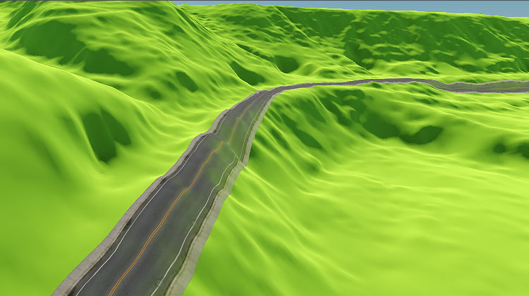
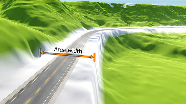
Collider Flag indicating whether collisions for the generated object are to be detected or not. NoticeAvailable only for geometry type.Drop to ground Flag indicating whether the generated object will be aligned with the terrain surface or not. Height offset Distance from the terrain surface along the Z-axis, in units. NoticeIf you see the generated object partially, You can try to increase this value to lift it above the terrain surface.Decal texture resolution Resolution of baked texture for decals. NoticeAvailable only for decal type.Split segments Flag indicating whether the segment splitting mode is enabled. In this mode all spline segments will be divided into subsegments of the specified length (if this length does not exceed the length of the segment itself). NoticeThis parameter can be used to provide better alignment of spline objects with the terrain.Split segment length Length of the segment for splitting mode, in units. NoticeThe lower the value the more segments will be generated. Setting too low values may significantly reduce performance.Split splines Flag indicating whether spline splitting mode is enabled. By default a single WorldSplineGraph object shall be generated for the specified tag and shall include all relevant geometry and/or decals. When spline splitting mode is enabled the spline will be divided into parts of the specified length (if this length does not exceed the length of the spline itself). Each part will be represented by a separate WorldSplineGraph object. NoticeThis parameter can be used to optimize performance. Generation of several WorldSplineGraph objects instead of a single one makes it possible to use the advantages of managing visibility distances (according to LOD settings of the basic mesh).Split splines length (km) Length of the spline for splitting mode, in kilometers. NoticeThe lower the value the more splines will be generated. Setting too low values may significantly reduce performance.Adjust terrain heights and masks Flag indicating whether terrain heights and masks will be adjusted for generated roads. When this option is enabled the following data of the global terrain will be modified in the areas along the splines having the width specified by the Area width parameter: height data will be adjusted (flattened) to provide better alignment of generated roads with the terrain surface.
- masks data will be cut out (e.g. preventing grass from growing on roads).NoticeAll masks will be affected.
NoticeEnabling this option significantly increases generation time.
-
Adjustment will affect all height and mask LOD's of the global terrain having the density satisfying the following condition:
Density < Area width x 6.
Area width Width of the area along the spline to be affected by heights and masks adjustment. NoticeAvailable only when heights and masks adjustment is enabled.Forward axis Axis along which the basic mesh is to be extruded or tiled. Mode One of the following: - Stretch - in this case the basic mesh will be extruded along spline segments.
- Tiling - in this case the basic mesh will be tiled along spline segments.
NoticeIf the Stretch mode is selected the number of meshes in the generated object is significantly lower which makes it more performance friendly. - Check the basic objects you added at the previous step to be generated.
NoticeIf you are going to update some of the existing spline objects, check only the changed ones. At that, the other objects will remain the same after terrain generation.
-
Now all necessary basic objects are specified and bound to tags.
NoticeIf the terrain is already generated and you want to add only spline objects - proceed to Step 4.
Otherwise - return back to setting other parameters of terrain generation.
4. Generating Spline Objects#
Now you can generate spline objects by clicking Generate button and selecting Vector objects option in the Steps window, in this case only vector objects will be generated.
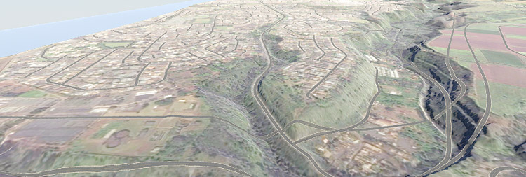
Here is a terrain fragment with roads generated on the basis of vector data using the basic mesh object we created.
To regenerate some of the existing spline objects, check only those objects that should be updated, click Generate and select Vector objects option. Only the specified spline objects will be regenerated. At that, the other ones (that haven't been checked) will remain the same.
