World Spline Graph
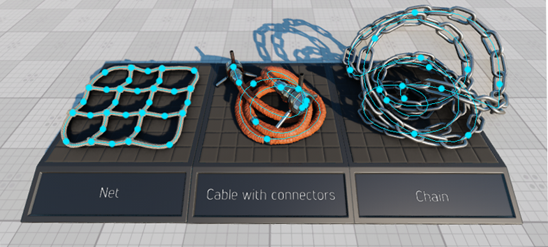
World spline graph is a convenient and performance-friendly method to place specified nodes (called source nodes) along a spline graph (its vertices and edges). It is not a single-purpose tool designed just to create roads. It can also be used for ropes, chains, pipes, and any objects, having a form that follows a curved path. It is designed to help artists quickly build various complex structures from typical basic elements placed along spatial curves, such as pipes and tubes at an oil refinery, for example. World Spline Graph - это удобный и эффективный метод размещения указанных нод (называемых исходными нодами ) вдоль сплайн-графа (его вершин и ребер). Это не одноцелевой объект, предназначенный только для создания дорог. Его также можно использовать для веревок, цепей, труб и любых объектов, имеющих форму, повторяющую изогнутую траекторию. Он разработан, чтобы помочь художникам быстро создавать различные сложные конструкции из типичных базовых элементов, расположенных вдоль пространственных кривых, таких как, например, трубы на нефтеперерабатывающем заводе.
A spline graph is determined by a set of points p0, p1, ... pn and a set of edges or segments (cubic Bezier splines), that connect some or all of these points.Сплайн-граф определяется набором точек p0, p1, ... pn и набором ребер или сегментов (кубические сплайны Безье), которые соединяют некоторые или все эти точки.
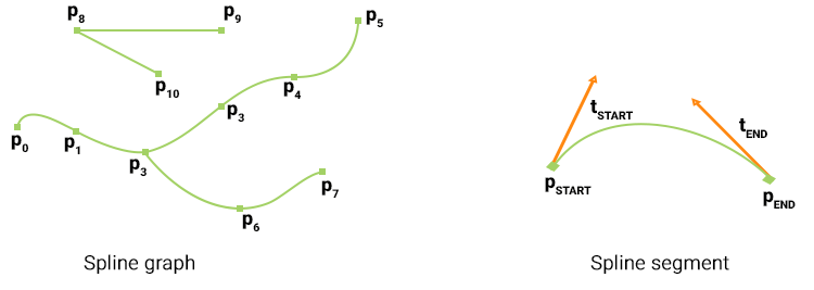
Each segment is determined by a starting (pSTART) and an ending (pEND) point, as well as tangent vector coordinates at these points, which determine the curvature of the segment (tSTART and tEND respectively). Points, that are shared by more than two segments are called junctions.Каждый сегмент определяется начальной (pSTART) и конечной (pEND) точкой, а также координатами касательного вектора в этих точках, которые определяют кривизну сегмента (tSTART и tEND соответственно). Точки, которые используются более чем двумя сегментами, называются перекрестки .
Source nodes (currently Static Mesh, Skinned Mesh, and Projected Decal) can be placed at points and along the segments of the spline graph. Each point and segment can have a single or a set of source nodes assigned. One of the following modes can be selected for each individual source node assigned to a segment: Базовые ноды (в настоящее время Static Mesh, Skinned Mesh и Projected Decal) могут быть размещены в точках и вдоль сегментов сплайн-графа. Каждой точке и сегменту может быть назначен одна базовая нода или набор таковых. Для каждой отдельной базовой ноды, назначенного сегменту, можно выбрать один из следующих режимов:
- stretching - source nodes are stretched along the spline segment.ПримечаниеStretching is available only for Static Mesh source nodes.stretching - базовые ноды растянуты по отрезку сплайна.Stretching is available only for Static Mesh source nodes.Stretching is available only for Static Mesh source nodes.ПримечаниеStretching is available only for Static Mesh source nodes.Режим Stretching доступен только для статических сеток.
- tiling - source nodes are duplicated along the spline segment.tiling - базовые ноды дублируются вдоль сегмента сплайна.
- adaptive (a combination of the first two) - source nodes are duplicated along the spline segment, but the length of each node (stretching) is determined by the curvature of the corresponding part of the segment. Thus, long nodes are placed along the straight parts of segments, while short ones - along the curved parts, providing a reasonable balance between the plausible look and performance.adaptive (комбинация первых двух) - исходные узлы дублируются вдоль сегмента сплайна, но длина каждой ноды (растяжения) определяется кривизной соответствующей части сегмента. Таким образом, длинные ноды размещаются вдоль прямых частей сегментов, а короткие - вдоль изогнутых частей, обеспечивая разумный баланс между правдоподобным видом и производительностью.
For example, a segment can have two source nodes assigned: one representing the road (stretched) and another for roadway lights (tiled with a gap). Например, сегменту могут быть назначены две базовых ноды: одна, представляющий дорогу (растянутый), а другая - для фонарей проезжей части (выложенный плиткой с зазор ).
An arbitrary number of WorldSplineGraph nodes can be added to the scene as it uses a number of optimizations (such as baking elements into large segments etc.) to ensure acceptable performance for large areas.В сцену может быть добавлено произвольное количество нод WorldSplineGraph, поскольку она использует ряд оптимизаций (например, запекание элементов в большие сегменты и т. д.) Для обеспечения приемлемой производительности для больших площадей.
Coordinates of the UP vector are additionally stored for each point of the segment. This vector is used to define orientation of nodes placed along the segments of the spline graph. By default this vector is parallel to the Z axis. The UP vector does not affect the curvature of the spline segment itself. Координаты вектора UP дополнительно сохраняются для каждой точки сегмента. Этот вектор используется для определения ориентации нод, расположенных вдоль сегментов сплайн-графа. По умолчанию этот вектор параллелен оси Z. Вектор ВВЕРХ не влияет на кривизну самого сегмента сплайна.
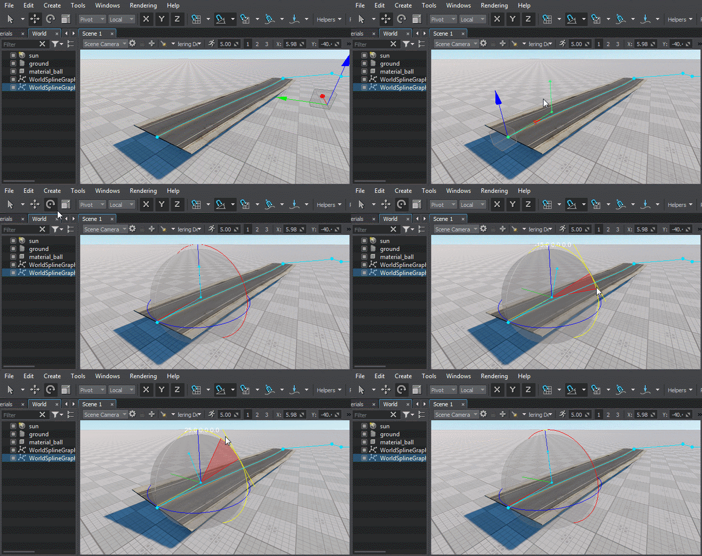
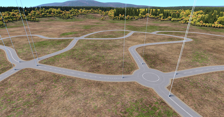
SDK includes the Road Tool Constructor add-on with a set of ready-to-use assets (road segments and various types of junctions) that can be used as construction elements to simplify roads creation. SDK включает надстройку Road Tool Constructor с набором готовых к использованию ресурсов (участки дорог и различные типы перекрестков), которые можно использовать в качестве строительных элементов для упрощения создания дорог.
- it cannot be converted to a Node Reference.it cannot be converted to a Node Reference.
- it is not supported by Node Layers.it is not supported by Node Layers.
- it cannot be converted to a Node Reference.он не может быть преобразован в Node Reference.
- it is not supported by Node Layers.он не поддерживается Node Layers.
See alsoСмотрите также#
- The WorldSplineGraph class article to learn how to manage world spline graphs via APIСтатья о классе WorldSplineGraph, чтобы узнать, как управлять мировыми сплайн-графами через API
- The SplinePoint class article to learn how to manage spline graph points via APIСтатья о классе SplinePoint, чтобы узнать, как управлять точками сплайнового графа через API.
- The SplineSegment class article to learn how to manage spline graph segments via APIСтатья о классе SplineSegment, чтобы узнать, как управлять сегментами сплайн-графа через API
- C++ sample for the WorldSplineGraph class illustrating how to manage spline graphs and generate geometry along the graph segments: source/samples/Api/Nodes/WorldSplineGraphПример C ++ для класса WorldSplineGraph, показывающий, как управлять сплайн-графами и генерировать геометрию по сегментам графа: source / samples / Api / Nodes / WorldSplineGraph
- Samples illustrating use cases of the WorldSplineGraph node included in the Samples suite:
- world_spline_graph/roads - roads created on the terrain surfaceworld_spline_graph/roads - roads created on the terrain surface
- world_spline_graph/ropes - ropes, chains, and cablesworld_spline_graph/ropes - ropes, chains, and cables
- world_spline_graph/roads - roads created on the terrain surfaceworld_spline_graph/roads - дороги, созданные на поверхности местности
- world_spline_graph/ropes - ropes, chains, and cablesworld_spline_graph/ropes - канаты, цепи и тросы
Creating a World Spline GraphСоздание World Spline Graph#
To create a new World Spline Graph, do the following:Чтобы создать новый World Spline Graph, сделайте следующее:
- Add a World Spline Graph node: on the Menu Bar, choose Create -> Spline Graph.
Добавить ноду World Spline Graph: в Меню , выберите Create -> Spline Graph.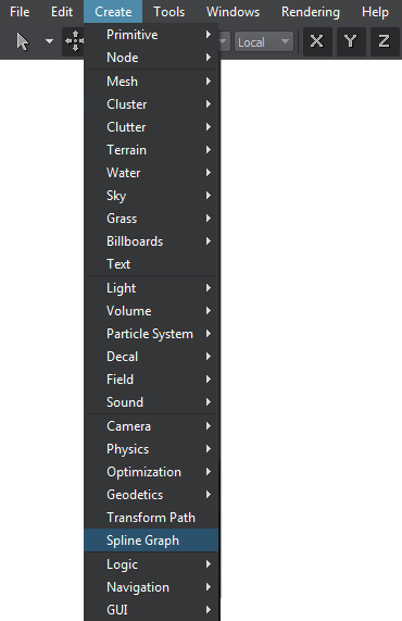

- Specify a name of existing spline file (*.spl) to be used for the new World Spline Graph or a new name to create your spline from scratch.
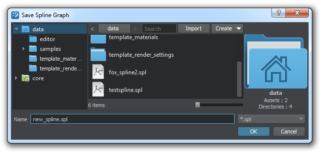 ПримечаниеRemember, *.world files store only WorldSplineGraph node's data (transformation, list of source nodes, etc.), while spline graphs themselves are stored in separate *.spl files. To save the spline graph that you created in the world, click Save Spline in the Parameters tab and specify a file name for it. Укажите имя существующего файла сплайна (*.spl), которое будет использоваться для нового World Spline Graph или новое имя, чтобы создать сплайн с нуля.Remember, *.world files store only WorldSplineGraph node's data (transformation, list of source nodes, etc.), while spline graphs themselves are stored in separate *.spl files. To save the spline graph that you created in the world, click Save Spline in the Parameters tab and specify a file name for it. Remember, *.world files store only WorldSplineGraph node's data (transformation, list of source nodes, etc.), while spline graphs themselves are stored in separate *.spl files. To save the spline graph that you created in the world, click Save Spline in the Parameters tab and specify a file name for it.
 ПримечаниеRemember, *.world files store only WorldSplineGraph node's data (transformation, list of source nodes, etc.), while spline graphs themselves are stored in separate *.spl files. To save the spline graph that you created in the world, click Save Spline in the Parameters tab and specify a file name for it. Помните, что файлы *.world хранят только данные ноды WorldSplineGraph(преобразование, список базовых нод и т.д.), В то время как сами сплайн-графы хранятся в отдельных файлах *.spl. Чтобы сохранить созданный вами в мире сплайн-граф, щелкните Save Spline на вкладке Parametersи укажите для него имя файла.
 - Edit the spline graph by managing its points and segments.Отредактируйте сплайн-граф, управляя его точки а также сегменты .
- Assign desired source nodes to points and segments of the spline graph.Назначать требуемые базовые ноды к точкам и сегментам сплайн-графа.
Managing PointsУправляющие точки#
Adding a New PointДобавление новой точки#
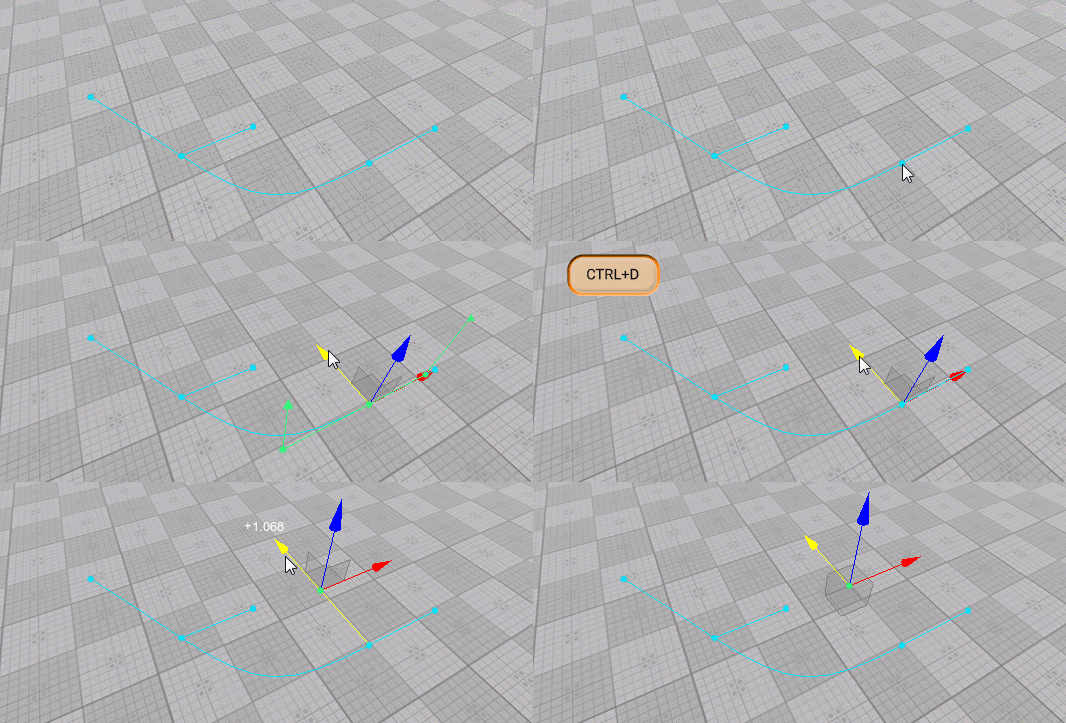
New points are added to the spline graph by cloninng existing ones. To add a new point do the following:Новые точки добавляются к сплайновому графу путем клонирования существующих. Чтобы добавить новую точку, сделайте следующее:
- Select the World Spline Graph.Выберите файл World Spline Graph.
- Select the desired point, which you wish to clone (Move manipulator will appear).Выберите желаемую точку, которую хотите клонировать (появится манипулятор Move).
- Press Ctrl + D on the keyboard (a new point will be created).Нажмите Ctrl + D на клавиатуре (будет создана новая точка).
- Use the Move manipulator to position you new created point.Используйте манипулятор Move, чтобы расположить новую созданную точку.
Adjusting Point's PositionРегулировка положения точки#
To adjust position of a point do the following:Чтобы настроить положение точки, выполните следующие действия:
- Select the World Spline Graph.Выберите файл World Spline Graph.
- Select the desired point (Move manipulator will appear).Выберите нужную точку (появится манипулятор Move).
- Use the Move manipulator as you would do to move a node.Используйте манипулятор перемещения, как если бы вы перемещали ноду.
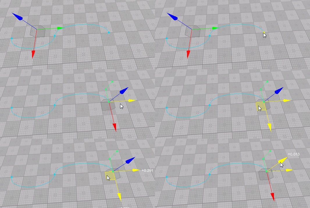
You can also adjust the position of the selected point via the Spline Points section of the Parameters tab:Вы также можете настроить положение выбранной точки через раздел Spline Points вкладки Parameters:

Adjusting Point's TangentРегулировка касательной точки#
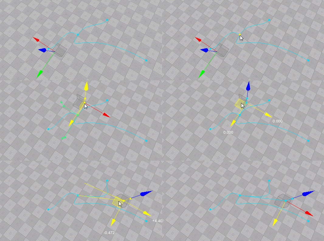
Tangents control the curvature of the spline segment. To adjust tangent at a point do the following:Касательные определяют кривизну сегмента сплайна. Чтобы скорректировать касательную в точке, сделайте следующее:
- Select the World Spline Graph.Выберите файл World Spline Graph.
- Select the desired point (Move manipulator will appear).Выберите нужную точку (появится манипулятор Move).
- Select the desired tangent (in case the selected point is shared by multiple segments, several tangents will be displayed for it). As you select a tangent the Move manipulator appears next to it.Выберите желаемую касательную (если выбранная точка является общей для нескольких сегментов, для нее будет отображаться несколько касательных). Когда вы выбираете касательную, рядом с ней появляется манипулятор перемещения.
- Use the Move manipulator as you would do to move a node (the form of the corresponding segment will change).Используйте манипулятор Move, как если бы вы перемещали ноду (форма соответствующего сегмента изменится).
Adjusting Point's UP VectorРегулировка вектора UP точки#
Up vector controls orientation of nodes placed along the spline segment. To adjust tangent at a point do the following:Вектор вверх управляет ориентацией нод, расположенных вдоль сегмента сплайна. Чтобы скорректировать касательную в точке, сделайте следующее:
- Select the World Spline Graph.Выберите файл World Spline Graph.
- Select the desired point (Move manipulator will appear).Выберите нужную точку (появится манипулятор Move).
- Select the desired UP vector (in case the selected point is shared by multiple segments, several UP vectors will be displayed for it).Выберите желаемый вектор ВВЕРХ (если выбранная точка является общей для нескольких сегментов, для нее будет отображаться несколько векторов ВВЕРХ).
- Switch to Rotate manipulator and use it to adjust the desired angle as you would do to rotate a node (the orientation of nodes placed along the corresponding segment will change).ПримечаниеYou'll be able to see the effect only when a node is assigned to the corresponding segment.Переключитесь на манипулятор поворота и используйте его для регулировки желаемого угла, как если бы вы вращали ноду (ориентация нод, размещенных вдоль соответствующего сегмента, изменится).You'll be able to see the effect only when a node is assigned to the corresponding segment.You'll be able to see the effect only when a node is assigned to the corresponding segment.ПримечаниеYou'll be able to see the effect only when a node is assigned to the corresponding segment.Вы сможете увидеть эффект только тогда, когда нода будет назначен соответствующему сегменту.
- Use the Move manipulator as you would do to move a node (the form of the corresponding segment will change).Используйте манипулятор Move, как если бы вы перемещали ноду (форма соответствующего сегмента изменится).

Merging PointsСлияние точек#
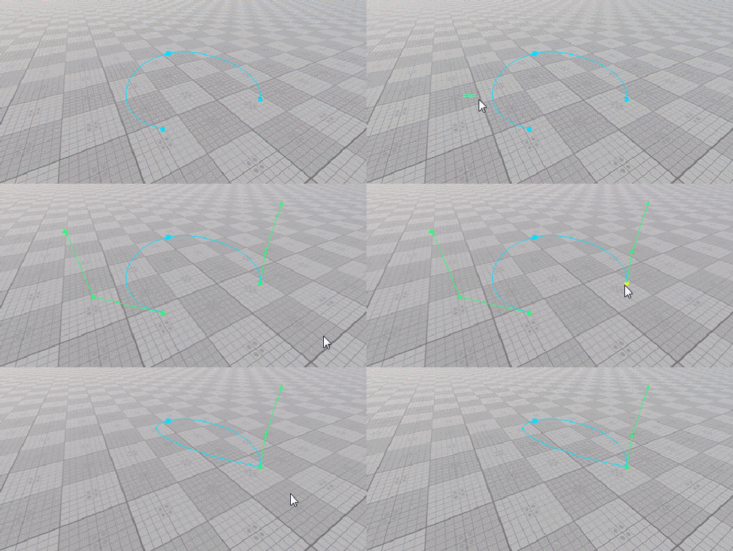
Sometimes it might be necessary to merge certain points (e.g. to close a spline). To merge two or more points into one do the following:Иногда может потребоваться объединить определенные точки (например, чтобы замкнуть сплайн). Чтобы объединить две или более точек в одну, выполните следующие действия:
- Select the World Spline Graph.Выберите файл World Spline Graph.
- Select points you want to merge with a region selection tool or one-by-one while holding the Shift key pressed.Выберите точки, которые вы хотите объединить, с помощью инструмента выделения области или по одной, удерживая нажатой клавишу Shift.
- Right-click on a point you want to merge selected ones into and choose Merge To This Point.Щелкните правой кнопкой мыши точку, в которую вы хотите объединить выбранные, и выберите Merge To This Point.
- All points will be merged into one shared by the segments, to which the merged points belonged.Все точки будут объединены в одну общую для сегментов, которым принадлежали объединенные точки.
Deleting a PointУдаление точки#
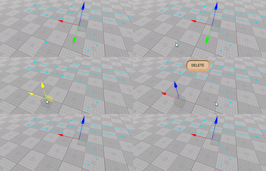
To delete point(s) of the spline graph do the following:Чтобы удалить точку (точки) сплайн-графика, выполните следующие действия:
- Select the World Spline Graph.Выберите файл World Spline Graph.
- Select point(s) you want to delete with a region selection tool or one-by-one while holding the Shift key pressed.Выберите точки, которые вы хотите удалить, с помощью инструмента выделения области или одну за другой, удерживая нажатой клавишу Shift.
- Press the Del key.Нажмите клавишу Del .
Managing SegmentsУправление сегментами#
Adding a New SegmentДобавление нового сегмента#
To add a new segment to the spline graph do the following:Чтобы добавить новый сегмент к сплайновому графику, выполните следующие действия:
- Select the World Spline Graph.Выберите файл World Spline Graph.
- Select the starting point for the new segment to be added (Move manipulator will appear).Выберите начальную точку для добавления нового сегмента (появится манипулятор перемещения).
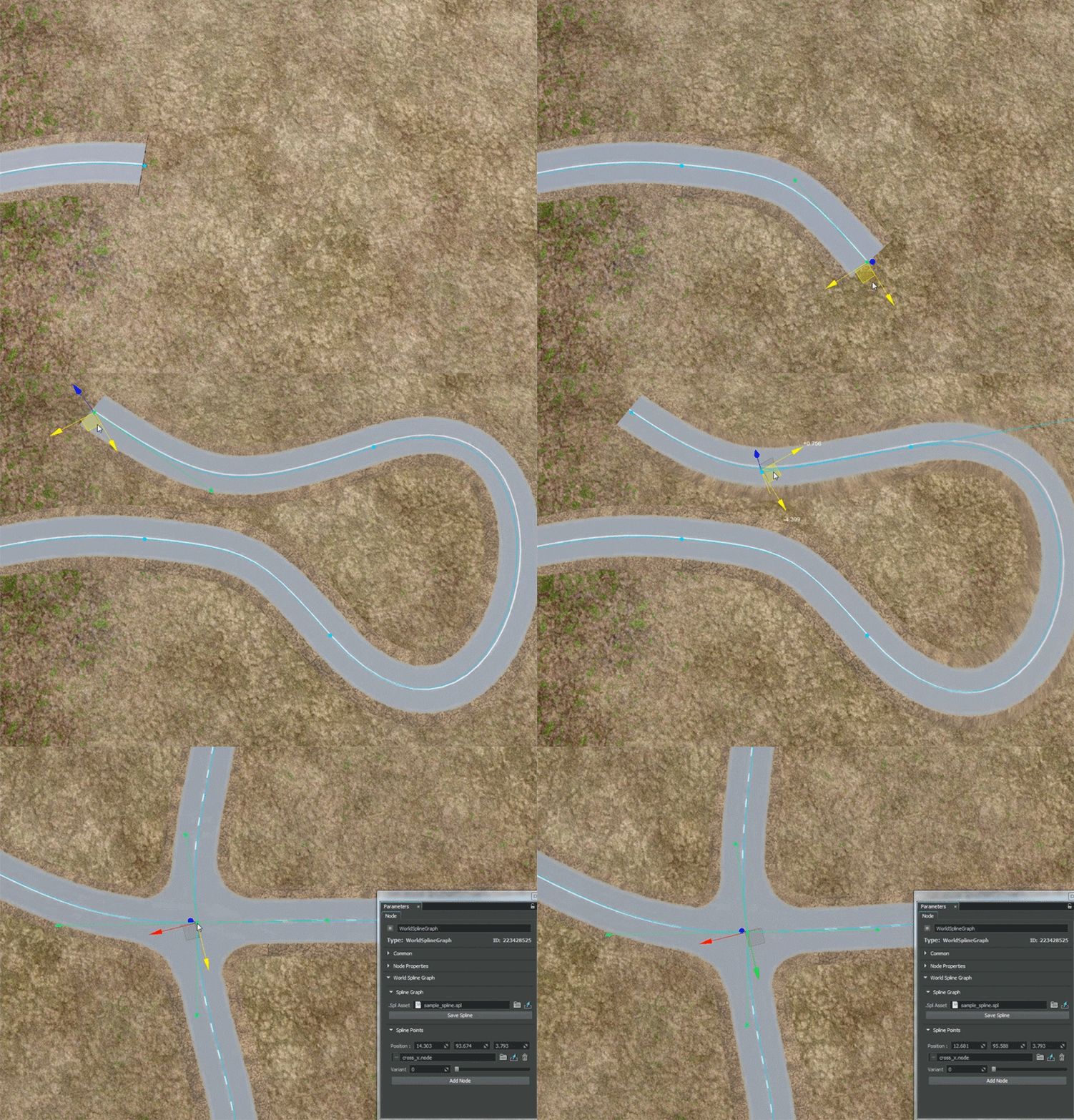
- Press and hold the Shift key and use the Move manipulator to position the ending point of the new segment.ПримечаниеTo create a straight segment, you should drag the manipulator in the direction of the tangent at the starting point.The new added segment uses all settings (assigned nodes, placement modes and parameters) of the previous one.Нажмите и удерживайтеShiftи используйте манипулятор Move, чтобы расположить конечную точку нового сегмента.
- To create a straight segment, you should drag the manipulator in the direction of the tangent at the starting point.To create a straight segment, you should drag the manipulator in the direction of the tangent at the starting point.
- The new added segment uses all settings (assigned nodes, placement modes and parameters) of the previous one.The new added segment uses all settings (assigned nodes, placement modes and parameters) of the previous one.
Примечание- To create a straight segment, you should drag the manipulator in the direction of the tangent at the starting point.Чтобы создать прямой сегмент, вы должны перетащить манипулятор в направлении касательной в начальной точке.
- The new added segment uses all settings (assigned nodes, placement modes and parameters) of the previous one.Новый добавленный сегмент использует все настройки (назначенные нодв, режимы размещения и параметры) предыдущего.
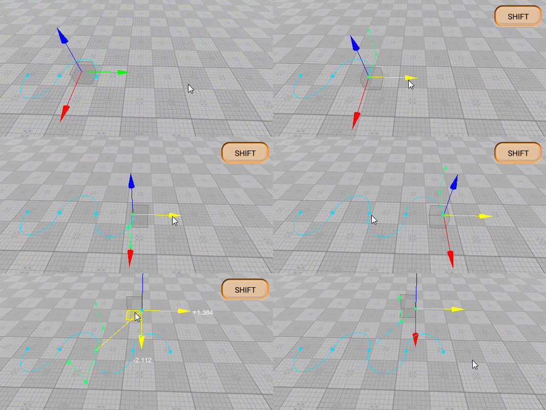
You can also clone segment(s) by selecting them and moving with the Shift key pressed, or pressing Ctrl + D and placing the clone with the Move manipulator.Вы также можете клонировать сегменты, выделив их и переместив с нажатой клавишей Shift, или нажав Ctrl + D и поместив клон с помощью манипулятора Move.
Deleting a SegmentУдаление сегмента#
To delete segment(s) of the spline graph do the following:Чтобы удалить сегмент (-ы) сплайн-графика, выполните следующие действия:
- Select the World Spline Graph.Выберите файл World Spline Graph.
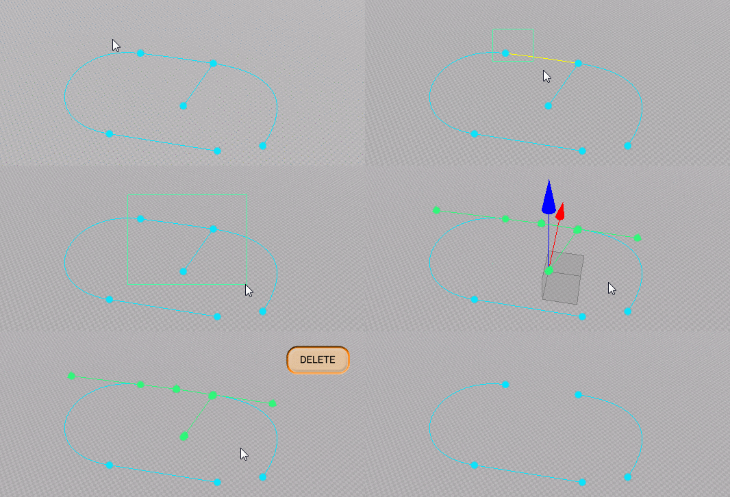
- Select segment(s) you want to delete with a region selection tool or one-by-one while holding the Shift key pressed.Выделите сегменты, которые вы хотите удалить, с помощью инструмента выделения области или по одному, удерживая нажатой клавишу Shift.
- Press the Del key.Нажмите клавишу Del .
Managing Source NodesУправление исходными нодами#
As described above, a single or a set of source nodes can be assigned to each point or segment of the spline graph.Как описано выше, один или набор исходных нод может быть назначен каждой точке или сегменту сплайнового графика.
Workflow for SegmentsРабота с сегментами#
To assign a source node to selected segment(s) do the following:Чтобы назначить базовую ноду выбранным сегментам, выполните следующие действия:
- Select the desired segments(s).Выберите желаемые сегменты.
- Click Add Node in the Parameters tab.Щелкните Add Node на вкладке Parameters.
- In the window that opens, select the required node and click OK.ПримечаниеSource nodes to be assigned to segments and points are stored in *.node files. The node file should contain a Static Mesh, Skinned Mesh, or Projected Decal as a root node.В открывшемся окне выберите нужную ноду и нажмите OK.Source nodes to be assigned to segments and points are stored in *.node files. The node file should contain a Static Mesh, Skinned Mesh, or Projected Decal as a root node.Source nodes to be assigned to segments and points are stored in *.node files. The node file should contain a Static Mesh, Skinned Mesh, or Projected Decal as a root node.ПримечаниеSource nodes to be assigned to segments and points are stored in *.node files. The node file should contain a Static Mesh, Skinned Mesh, or Projected Decal as a root node.Базовые ноды, которые должны быть назначены сегментам и точкам, хранятся в файлах *.node. Файл ноды должен содержать Static Mesh, Skinned Mesh или Projected Decal в качестве корневой ноды.
For each of the source nodes assigned to the selected segment(s) the following settings are available for adjustment via the Parameters tab:Для каждой из базовых нод, назначенных выбранному сегменту (-ам), на вкладке Parameters доступны следующие настройки:
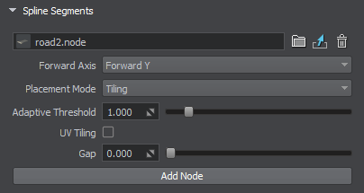
| Node | Path to a *.node file containing a source node.Путь к файлу *.node, содержащему базовую ноду. |
|---|---|
| Forward Axis | Defines which axis of the source node is to be oriented along the spline.Определяет, какая ось базовой ноды должна быть ориентирована вдоль сплайна. |
| Placement Mode | Type of objects to be generated. One of the following:
Примечание This mode is the most performance-friendly.Tiling - multiple instances of the source node are placed along the segment. The number of instances is determined by the sizes of the segment and the source node and the value of the Gap parameter.Adaptive - a combination of the previous two resulting in multiple instances of the source node placed along the segment. Some of these instances may be stretched depending on segment's curvature.Тип создаваемых объектов. Одно из следующих:
This mode is the most performance-friendly.This mode is the most performance-friendly.
|
| Adaptive Threshold | Determines how much a source node's instance can be stretched in the Adaptive placement mode to cover the whole length of the segment. Примечание Available for Adaptive placement mode only.Определяет, насколько можно растянуть экземпляр базовой ноды в режиме размещения Adaptive, чтобы покрыть всю длину сегмента.Available for Adaptive placement mode only.Available for Adaptive placement mode only. Примечание Available for Adaptive placement mode only.Доступно только для режима размещения Adaptive. |
| UV Tiling | Enables tiling of the source node's textures.Включает мозаику текстур базовой ноды. |
| Gap | Defines the gap (in units) between the adjacent instances on the source node for the Tiling placement mode. Примечание Available for Tiling placement mode only.Определяет зазор (в единицах) между соседними экземплярами на базовой ноде для режима размещения Tiling.Available for Tiling placement mode only.Available for Tiling placement mode only. Примечание Available for Tiling placement mode only.Доступно только для режима размещения Tiling. |
Workflow for PointsРабота с точками#
To assign a source node to selected point(s) do the following:Чтобы назначить базовую ноду выбранной точке (точкам), выполните следующие действия:
- Select the desired point(s).Выберите желаемую точку (точки).
- Click Add Node in the Parameters tab.Щелкните Add Node на вкладке Parameters.
- In the window that opens, select the required node and click OK.
ПримечаниеFor a junction point to behave properly an ObjectMeshSkinned node should be assigned, and the number of its bones should correspond to the number of spline segments connected to this point.В открывшемся окне выберите нужную ноду и нажмите OK.For a junction point to behave properly an ObjectMeshSkinned node should be assigned, and the number of its bones should correspond to the number of spline segments connected to this point.For a junction point to behave properly an ObjectMeshSkinned node should be assigned, and the number of its bones should correspond to the number of spline segments connected to this point.ПримечаниеFor a junction point to behave properly an ObjectMeshSkinned node should be assigned, and the number of its bones should correspond to the number of spline segments connected to this point.Что касается перекрестков, то для правильного поведения точке должен быть назначена нода ObjectMeshSkinned, а количество ее костей должно соответствовать количеству сегментов сплайна, подключенных к этой точке.
For each of the source nodes assigned to the selected point(s) the following settings are available for adjustment via the Parameters tab:Для каждой из базовых нод, назначенных выбранной точке (точкам), на вкладке Parameters доступны следующие настройки:
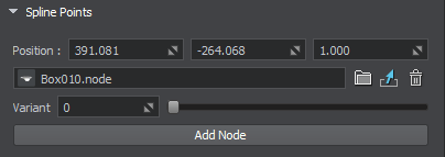
| Node | Path to a *.node file containing a source node.Путь к файлу *.node, содержащему базовую ноду. |
|---|---|
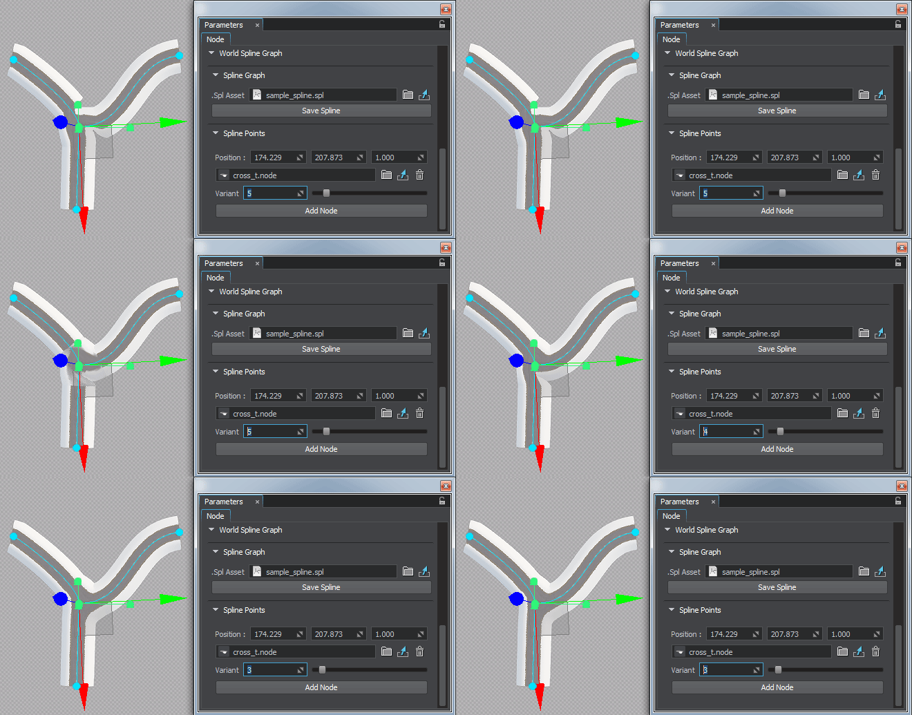
| Variant | There is a number of possible variants for a junction. This slider enables you to choose the one that fits best. Примечание
This parameter affects only the source nodes representing junctions (ObjectMeshSkinned).This parameter affects only the source nodes representing junctions (ObjectMeshSkinned).
Примечание
This parameter affects only the source nodes representing junctions (ObjectMeshSkinned).Этот параметр влияет только на базовые ноды, представляющие соединения (ObjectMeshSkinned).
|
JunctionsПерекрестки#
Junctions should interact with all entering segments properly providing seamless transitions. For this puprose ObjectMeshSkinned source nodes are used.Перекрестки должны правильно взаимодействовать со всеми входящими сегментами, обеспечивая плавные переходы. Для этого используются базовые ноды ObjectMeshSkinned.
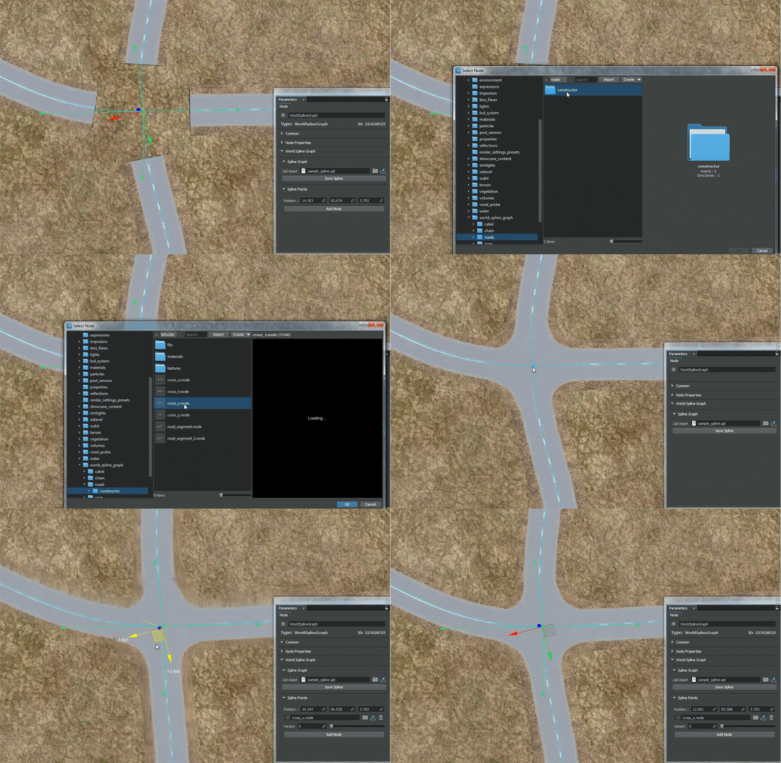
Source nodes to be used for junctions must comply with the following requirements:Базовые ноды, которые будут использоваться для соединений, должны соответствовать следующим требованиям:
- Joints of a junction in the UnigineEditor must have their Y axes oriented from the center of the junction to the edges of the corresponding branches.Соединения соединения в UnigineEditor должны иметь оси Y, ориентированные от центра соединения к краям соответствующих ответвлений.
- Outer joint of each junction’s branch must be placed exactly at the center of its outer edge, weights for outer vertices of the branch must be maximal for the outer joint (i.e., outer vertices of the branch are affected only by the outer joint).Внешний стык каждого ответвления должен быть размещен точно в центре его внешнего края, веса для внешних вершин ответвления должны быть максимальными для внешнего стыка (т. Е. На внешние вершины ответвления влияет только внешний стык).
- As junction and segment are represented by separate meshes, textures and their UV maps must ensure seamless junction-segment and segment-segment transitions.Поскольку соединение и сегмент представлены отдельными сетками, текстуры и их карты UVдолжны обеспечивать плавные переходы между сегментами и сегментами.
- A segment may have junctions at both of its endpoints, Therefore the texture used for the segment must be symmetrical, at least its edges.Сегмент может иметь соединения на обоих концах, поэтому текстура, используемая для сегмента, должна быть симметричной, по крайней мере, ее края.
- Specific requirements for roads:
- A junction as well as a road segment must be represented by a pair of meshes (embankment and the road itself). Embankment mesh is used for smooth blending with terrain surface. Just enable the Terrain Lerp state for the material assigned to embankment.A junction as well as a road segment must be represented by a pair of meshes (embankment and the road itself). Embankment mesh is used for smooth blending with terrain surface. Just enable the Terrain Lerp state for the material assigned to embankment.
- To ensure correct deformation of segments and junctions triangulation for the road and embankment must match. This prevents penetration of meshes into each other when moving spline points up and down.To ensure correct deformation of segments and junctions triangulation for the road and embankment must match. This prevents penetration of meshes into each other when moving spline points up and down.
- A junction as well as a road segment must be represented by a pair of meshes (embankment and the road itself). Embankment mesh is used for smooth blending with terrain surface. Just enable the Terrain Lerp state for the material assigned to embankment.Перекресток, а также участок дороги должны быть представлены парой сеток (насыпь и сама дорога). Сетка насыпи используется для плавного перехода с поверхностью ландшафта. Просто включите состояние Terrain Lerpдля материала, назначенного насыпи.
- To ensure correct deformation of segments and junctions triangulation for the road and embankment must match. This prevents penetration of meshes into each other when moving spline points up and down.Для обеспечения правильной деформации сегментов и перекрестков триангуляция дороги и насыпи должна совпадать. Это предотвращает проникновение сеток друг в друга при перемещении точек шлицев вверх и вниз.
Exporting World Spline GraphЭкспорт World Spline Graph#
World Spline Graph works well as a tool for object placement and deformation, but due to some technical issues, it is difficult to use it in final applications as the resulting object. Therefore, as soon as the object arrangement is final, it is required to export the spline graph to the .mesh or .fbx file.World Spline Graph хорошо работает как инструмент для размещения и деформации объектов, но из-за некоторых технических проблем его сложно использовать в конечных приложениях в качестве результирующего объекта. Поэтому, как только расположение объектов окончательное, требуется экспортировать сплайн-граф в файл .mesh или .fbx.
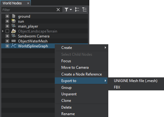
To export World Spline Graph, right-click it in the World Nodes hierarchy, select Export to and a preferable option:Чтобы экспортировать World Spline Graph, щелкните его правой кнопкой мыши в иерархии World Nodes, выберите Export to и предпочтительный вариант:
The export operation produces unique geometry that you can use in your projects like any other model without any additional restrictions.Операция экспорта создает уникальную геометрию, которую вы можете использовать в своих проектах, как и любую другую модель, без каких-либо дополнительных ограничений.
LimitationsОграничения#
Due to the nature of the mesh, there will be visual artifacts connected with the float precision, if World Spline Graph is exported to a very big object (around 10,000 m from the origin to either side). We recommend splitting such big objects to smaller ones.Из-за природы сетки будут визуальные артефакты, связанные с точностью плавания, если World Spline Graph экспортируется в очень большой объект (около 10 000 м от начала координат в обе стороны). Мы рекомендуем разбивать такие большие объекты на более мелкие.
A problem may also arise if World Spline Graph, though being not very big, is located very far from the origin (around 10,000 m and further). In this case we advise exporting it to FBX without storing pivot (the Save root transform option should be disabled), or resetting the World Spline Graph position to origin before exporting it to Mesh.Проблема может возникнуть и в том случае, если World Spline Graph хоть и не очень большой, но находится очень далеко от начала координат (около 10 000 м и дальше). В этом случае мы советуем экспортировать его в FBX, не сохраняя точку поворота (опция Save root transform должна быть отключена), или сбросить позицию World Spline Graph в исходное положение перед экспортом в Mesh.

