IG Aviation Add-on
The IG Aviation add-on contains a set of ready-to-use aircraft components creating such effects as engine and landing gear fire, smoke, contrail, landing gears, helicopter rotor blade settings with the blurring effect and rotor wash effect. The add-on also shows implementation of the wheel trace.
Components#
Aircraft Effects#
To set up various aircraft effects (engine or landing gear fire, smoke, contrail, etc.):
- Assign the EffectAircraftController property to the parent node (aircraft) and leave all parameters unchanged.
-
Assign the EffectAircraft property to each node representing visual effects of various types.
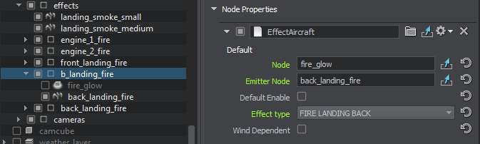
The following property parameters are available:
- Node — a node to be enabled/disabled
- Emitter Node — a node emitting particles for the effect
- Default Enable — indicates whether the effect should be enabled by default
- Effect Type — aircraft effect type selection (engine or landing gear fire, smoke, contrail, etc.)
- Wind Dependent — indicates whether the effect is affected by wind or not
Landing Gears#
This component allows controlling the landing gears. It contains several properties that shall be assigned as follows:
-
Assign the LandingGears property to the parent node (aircraft).
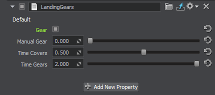
The following property parameters are available:
- Gear — indicates that gears are extended
- Time Covers — cover opening time, in seconds
- Time Gears — gear extension time, in seconds
NoticeMake sure all pivots are set up properly. -
Define which nodes represent parts of landing gears and assign the LandingGearPart property to them.
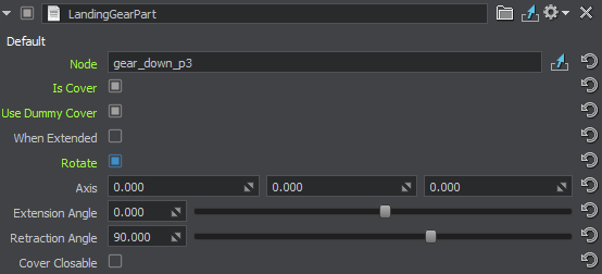
The following property parameters are available:
- Node — the node to be moved (usually the node to which this property is assigned)
- Is Cover — indicates whether the part is a cover or not (a cover is opened prior to gear extension)
-
Use Dummy Cover — indicates whether the wheel well is to be covered with a dummy cover after gear retraction. When enabled, an additional When Extended option is displayed. It is used to specify whether the dummy cover shall be visible when the gear is extended.
NoticeIf this option is enabled, the Node field should not contain the node to which this property is assigned, as the component will be disabled forever after retraction. - Rotate — indicates whether the part should rotate
- Axis — coordinates of the part's rotation axis
- Extension Angle — rotation angle of the part, when the gear is extended, in degrees
- Retraction Angle — rotation angle of the part, when the gear is retracted, in degrees
- Cover Closable — indicates whether the cover should close after gear extension, or to stay open
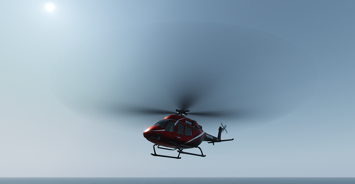
Rotor Blade#
The RotorBlade property controls the coning of the helicopter rotor blades and creates blurring to disk due to the blade rotation. To use this property, the rotor blade in your helicopter model should have a separate mesh and material.
Using this property also implies that you have the blade material (mesh_blade.mgraph in the add-on) and the node and material for circle into which the blades blur when rotating fast (check the disk node and mesh_blur_blades.mgraph material of the helicopter_simple Node Reference in the add-on).
Assign the RotorBlade property to the parent node (rotor node).
The following property parameters are available:

| Input | |
| Speed | Rotor rotation speed, in RPM. This is the default value that can be changed at runtime. |
|---|---|
| Beta 0 | Parameter defining the coning angle. This is the default value that can be changed at runtime. |
| Beta Cos | Parameter used for the longitudinal flapping. This is the default value that can be changed at runtime. |
| Beta Sin | Parameter used for the lateral flapping. This is the default value that can be changed at runtime. |
| Rotor | |
| Rotation Direction | Direction of the rotor rotation. |
| Pivot | Node to be rotated with the given RPM. |
| Axis | Rotation axis of the pivot node. |
| Blade | |
| Sample | Single blade sample. The model should have only one blade, the number of blades is controlled by the Total Count parameter. The blade should have its own mesh and material independent from the helicopter model body. The material should provide for the blade bending visualization. |
| Length | Blade length, in meters. |
| Total Count | Total number of rotor blades. The blade sample is cloned the required number of times, equally spaced, and arranged in a circle. |
| Material Beta 0 Parameter |
Name of the blade material parameter used to control the coning angle visualization. |
| Material Blade Length Parameter |
Name of the blade material parameter used to set the blade length. |
| Circle | |
| Node | The blurred circle node that replaces the blades at high RPM values. |
| Material Beta 0 Parameter |
Name of the circle material parameter used to control the coning angle visualization. |
| Material Beta Cos Parameter |
Name of the circle material parameter used to control the longitudinal flapping visualization. |
| Material Beta Sin Parameter |
Name of the circle material parameter used to control the lateral flapping visualization. |
| Material Blade Length Parameter |
Name of the circle material parameter used to set the blade length. |
| Material Blade Count Parameter |
Name of the circle material parameter used to set the blade count. |
| Material UV Animation Parameter |
Name of the circle material parameter used to control the circle UV animation depending on the rotor RPM value. |
| RPM To Time Coefficient |
Multiplier to translate the RPM value to the UV animation parameter value. |
| Blurring | |
| Threshold Blade Speed | Rotation speed before which only blades are visible, and starting from which the blades begin to blur. The bottom value of the rotation speed interval at which both the blades and the blurred circle are visible. |
| Threshold Circle Speed | Rotation speed starting from which only the blurred circle is rendered, the blades are no longer visible. The top value of the rotation speed interval at which both the blades and the blurred circle are visible. |
| Blade Alpha | Curve controlling the blade transparency during the interval at which both the blades and the blurred circle are visible. |
| Circle Alpha | Curve controlling the circle transparency during the interval at which both the blades and the blurred circle are visible. |
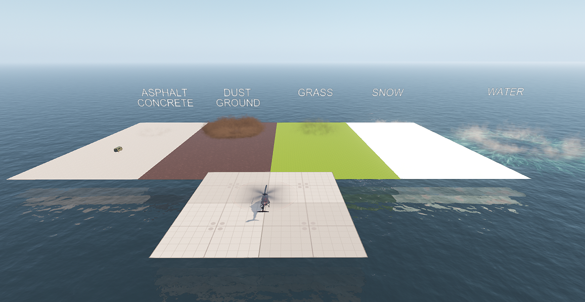
Rotor Wash Effect#
This component allows creating the effect of dust clouds raised up by the rotor wash when the helicopter is standing on the ground, taking off or landing, or flies close to the surface.
-
Create the effects for each type of surface in UNIGINE Editor and assign the RotorWashEffect property to each of them. The following parameters are available:
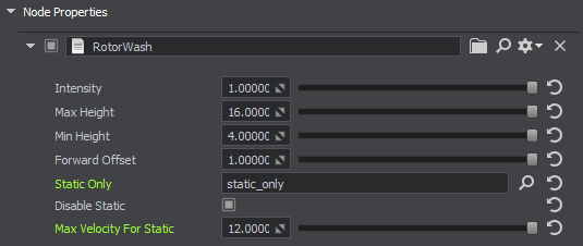
Intensity Rotor wash visibility intensity value. With the minimum value of 0 the effect is completely invisible. With the maximum value of 1 — completely visible. This is the default value that can be changed at runtime. Max Height Height of the node from the ground, at which the effect disappears. Min Height Height of the node from the ground, at which the effect has the maximum intensity. Forward Offset Multiplier to move the effect forward relative to the helicopter. The offset distance depends on the movement speed. This setting is intended to make the effect visible for the cockpit view. Static Only Root node for effects that are only displayed when the helicopter is not moving. Disable Static Disable the static effect node when the helicopter is moving. If the option is disabled (i.e. the static effect is enabled), the static effect is displayed throughout the whole life time of its particle systems. In most cases disabling this option (i.e. enabling the static effect visibility throughout the particles life time) is unnecessary, because the effect won’t be seen from the cockpit. Max Static Velocity Upper speed limit at which the helicopter is considered static (m/s). -
Assign the modifier depending on the effect node type: ParticlesParameterModifier / DecalParameterModifier / FieldHeightParameterModifier. The modifiers are required for the alignment of the corresponding node (Particles/Decal/FieldHeight) with the effect.
ParticlesParameterModifier has the following parameters:
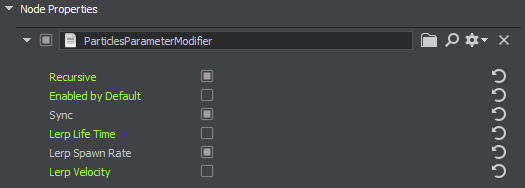
Recursive Toggles synchronization of child particle systems. Enabled by Default Toggles the node default state. If the node is disabled by default, you need to enable it via code after adding to the scene. Sync Synchronization of particles via Syncker. Recommended to enable only if synchronization via network is critical, because it may affect performance. Lerp Life Time Lerp the particles life time value with the effect intensity. If the effect intensity is equal to 0, the life time value also equals to 0. Lerp Spawn Rate Lerp the particles spawn rate value with the effect intensity. If the effect intensity is equal to 0, the spawn rate value also equals to 0. Lerp Velocity Lerp the particles velocity value with the effect intensity. If the effect intensity is equal to 0, the velocity value also equals to 0. -
Assign the RotorWashController property to the helicopter and select the type of surface corresponding to each effect.
-
Set the surface type via code for each surface.
Opening the World#
To open the world containing models:
- Install the IG Aviation add-on (available via UNIGINE SDK Browser in the Assets section) and add it to your project (by clicking Other Actions -> Configure Project -> Assets in the Projects section of UNIGINE SDK Browser).
- Click File -> Open World (Ctrl + O) or open the Asset Browser window, open the \ig_aircraft\sample_content folder, and select the ig_aircraft world. The scene will open.
The content in the \ig_aircraft\sample_content folder is designed to demonstrate how to use the properties. It may be deleted, if you don't need the demo scene and assets.
Configuring Your Project#
To add the IG Aviation add-on to your C++ project:
-
Install the IG Aviation add-on (available via UNIGINE SDK Browser in the Assets section) and add it to your project (by clicking Other Actions -> Configure Project -> Assets in the Projects section of UNIGINE SDK Browser).
Another way of adding the add-on to your project is to copy the following folders from this add-on to your project folder:
- data/ig_aircraft and data/properties to data
- source/ig_aircraft_components to source
- Add the source/ig_aircraft_components/* files to your C++ project.
- Build your application to register the added components in C++ Component System.
-
Configure ig_config.xml — add the following into the entity_types block:
Source code (XML)<entity id="201" name="be-200-mod"> <path>ig_aircraft/sample_content/be_200_mod.node</path> <component id="0" name="light_outer"> <property>LightAircraftController</property> <parameter type="int" name="data1">landing</parameter> <parameter type="int" name="data2">taxi</parameter> <parameter type="int" name="data3">navigation</parameter> <parameter type="int" name="data4">beacon</parameter> <parameter type="int" name="data5">strobe</parameter> <parameter type="int" name="data6">logo</parameter> </component> <component id="1" name="light_inner"> <property>LightAircraftController</property> <parameter type="int" name="data1">windows</parameter> <parameter type="int" name="data2">cockpit</parameter> </component> <component id="2" name="fire_engine"> <property>EffectAircraftController</property> <parameter type="int" name="data1">fire_engine_1</parameter> <parameter type="int" name="data2">fire_engine_2</parameter> <parameter type="int" name="data3">fire_engine_3</parameter> <parameter type="int" name="data4">fire_engine_4</parameter> </component> <component id="3" name="fire_aircraft"> <property>EffectAircraftController</property> <parameter type="int" name="data1">fire_landing_front</parameter> <parameter type="int" name="data2">fire_landing_back</parameter> <parameter type="int" name="data3">fire_tail</parameter> </component> <component id="4" name="landing_gears"> <property>LandingGears</property> <parameter type="int" name="data1">gear</parameter> <parameter type="float" name="data2">manual_gear</parameter> </component> <component id="5" name="effects"> <property>EffectAircraftController</property> <parameter type="int" name="data1">smoke</parameter> <parameter type="int" name="data2">contrail</parameter> </component> <articulated_part id="1" name="aileron"> <node invert_pitch="1">aileron_left</node> <node>aileron_right</node> </articulated_part> <articulated_part id="2" name="rudder"> <node invert_yaw="1">rudder</node> </articulated_part> <articulated_part id="3" name="elevator"> <node invert_pitch="1">flipper_left</node> <node invert_pitch="1">flipper_right</node> </articulated_part> <articulated_part id="4" name="flap"> <node invert_pitch="1">flap_0_left</node> <node invert_pitch="1">flap_0_right</node> <node invert_pitch="1">flap_1_left</node> <node invert_pitch="1">flap_1_right</node> </articulated_part> <articulated_part id="5" name="engine"> <node>engine_left</node> <node>engine_right</node> </articulated_part> <articulated_part id="6" name="wheel"> <node>chassis_element_left/chassis_left/wheels_left</node> <node>chassis_element_right/chassis_right/wheels_right</node> <node>dummy_axis_chassis_front/chassis_front001/wheels_front</node> </articulated_part> <articulated_part id="7" name="slat"> <node>slat_left</node> <node>slat_right</node> </articulated_part> <volume_definition id="0" name="body" shape="0">volumes</volume_definition> <volume_definition id="1" name="wings" shape="1">volumes</volume_definition> </entity> <entity id="180" name="uc-135"> <path>ig_aircraft/sample_content/helicopter/node/helicopter_simple.node</path> <component id="1" name="RotorBlade"> <node>body/rotor_aux</node> <property>RotorBlade</property> <parameter type="float" name="data1">speed</parameter> <parameter type="float" name="data2">beta_0</parameter> <parameter type="float" name="data3">beta_cos</parameter> <parameter type="float" name="data4">beta_sin</parameter> </component> <component id="2" name="RotorWashController"> <property>RotorWashController</property> <parameter type="float" name="data1">intensity</parameter> <parameter type="float" name="data2">rpm_intensity</parameter> </component> </entity> <entity id="218" name="minibus"> <path>ig_aircraft/sample_content/minibus/minibus.node</path> <component id="0" name="wheel_trace"> <property>WheelTraceController</property> <parameter type="float" name="data1">input_intensity</parameter> </component> </entity> - Configure your host. An example of host configuration may be found in the readme.md file.
In the configured project, you'll be able to create the following entity types:
- 201 — aircraft (fire effects, landing gears)
- 180 — helicopter (rotor coning, rotor wash)
- 218 — car (wheel trace decal)