Сочленения (Joints)
Joints provide constraints removing degrees of freedom from a body and are used to connect pairs of bodies. Each joint has an anchor point, which is by default placed between the centers of mass of connected bodies. The properties of each connection depend on the selected joint type and its parameters. Joint parameters can be divided into two groups: Сочленения (Joints) обеспечивают ограничения, ограничивающие степени свободы тела , и используются для соединения пар тел. У каждого сочленения есть точка привязки, которая по умолчанию размещается между центрами масс соединенных тел. Свойства каждого сочленения зависят от выбранного типа и его параметров. Параметры сочленений можно разделить на две группы:
- Common parameters - basic set of parameters shared by all joints. Общие параметры - базовый набор параметров, общий для всех сочленений.
- Type-specific parameters - a set of specific parameters for each joint type. Параметры для конкретного типа - набор конкретных параметров для каждого типа сочленения.
See alsoСмотрите также#
Programming implementation: Программная реализация:
- Joint class
- JointFixed class
- JointHinge class
- JointBall class
- JointPrismatic class
- JointCylindrical class
- JointWheel class
- JointSuspension class (устарело)
- JointPath class
- JointParticles class
Usage examples: Примеры использования:
- A Simple Mechanism Using Joints Простой механизм с использованием сочленениq
- Creating a Car with Wheel Joints Создание автомобиля с wheel-сочленениями
Fragment of video tutorial on physics about joints Фрагмент видеоурока по физике про сочленения
Adding a JointДобавление сочленения#
Assume you have two objects with physical bodies assigned. Remember that a body must have a shape assigned. To connect them using a joint via UnigineEditor, perform the following steps: Предположим, у вас есть два объекта с назначенными физическими телами. Помните, что телу (body) должна быть назначена форма (shape). Чтобы соединить их с помощью сочленения в UnigineEditor , выполните следующие шаги:
- Open the World Hierarchy window Откройте окно World Hierarchy
- Select the first body to connect Выберите первое тело для соединения
- Go to the Physics tab in the Parameters window. Перейдите на вкладку Physics в окне Parameters.
-
In the Joints section, choose an appropriate type of joint and click Add.
В разделе Joints выберите подходящий тип сочленения и щелкните Add.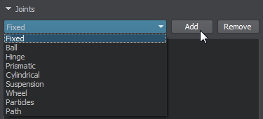

- Select the second body by picking its name in the dialog window and click Ok.
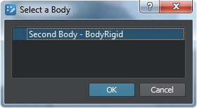 Выберите второе тело, указав его имя в диалоговом окне, и нажмите Ok.

- Set joint parameters in the Joints section. Задайте параметры сочленения в разделе Joints.
You can enable visualization of the joint by checking Helpers panel → Physics item → Joints option (Visualizer should be enabled). Вы можете включить визуализацию сочленения, выбрав панель Helpers → элемент Physics → параметр Joints (Visualizer должен быть включен).
Fixed JointFixed Joint#
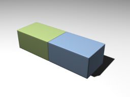
Fixed joints connect two bodies in a manner that strictly preserves their positions with respect to each other. Фиксированные сочленения соединяют два тела таким образом, чтобы их положение строго сохранялось по отношению друг к другу.
|
|
Fixed Joint
|

|
|
Fixed Joint Parameters Параметры Fixed Joint
|
The basic constraint parameters of this joint include: Основные параметры ограничения этого сочленения включают:
| Rotation 0 | Specifies orientation of the first body relative to the anchor point. Задает ориентацию первого тела относительно точки привязки. |
| Rotation 1 | Specifies orientation of the second body relative to the anchor point Задает ориентацию второго тела относительно точки привязки |
This joint also has a set of common parameters shared by all joint types. Это сочленения также имеет набор общих параметров , общих для всех типов сочленения.
For more information refer to JointFixed Class description. An example illustrating connection of two bodies using a fixed joint can be found here. Для получения дополнительной информации см. описание JointFixed Class. Пример, иллюстрирующий соединение двух тел с помощью фиксированного сочленения, можно найти здесь .
Watch the illustration of the Fixed joint in our video tutorial on physics. Посмотрите иллюстрацию фиксированного сочленения в нашем видеоуроке по физике .
Hinge JointHinge Joint#
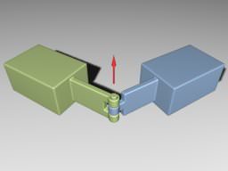
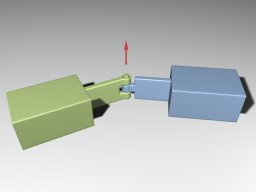
Hinge joints allow the connected bodies to rotate along the joint's axis at the anchor point. This joint has an angular motor attached. Шарнирные сочленения позволяют соединенным телам вращаться вдоль оси шарнира в точке привязки. К этому шарниру прикреплен угловой мотор .
|
|
|
Hinge Joint
|
|
|
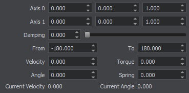
Hinge Joint Parameters Параметры Hinge Joint
|
The basic constraint parameters of this joint include: Основные параметры ограничения этого сочленения включают:
| Joint axis | Coordinates of the joint axis, around which the bodies rotate. Координаты оси сочленения, вокруг которой вращаются тела. |
| Angular damping | Angular damping coefficient of the hinge joint. Угловой коэффициент демпфирования шарнирного сочленения. |
| Angular limit from | Minimum angle in the range of movement at which the hinge stops. The angle is specified in degrees in the [-180; 180] range. Минимальный угол в диапазоне движения, при котором шарнир останавливается. Угол указывается в градусах в диапазоне [ -180 ; 180 ]. |
| Angular limit to | Maximum angle in the range of movement at which the hinge stops. The angle is specified in degrees in the [-180; 180] range. Максимальный угол в диапазоне движения, при котором шарнир останавливается. Угол указывается в градусах в диапазоне [ -180 ; 180 ]. |
| Angular spring | Spring rigidity coefficient, determines how strong the joint resists rotation. If rigidity is set to 0, the spring is disabled. Коэффициент жесткости пружины, определяет, насколько сильно сочленение сопротивляется вращению. Если жесткость установлена на 0 , пружина отключена. |
| Angular angle | Target angle of the attached angular spring. The spring (if it is enabled) tries to keep the specified angle between the connected bodies. Целевой угол прикрепленной угловой пружины. Пружина (если она включена) пытается сохранить заданный угол между соединенными телами. |
| Параметры двигателя | |
|---|---|
| Angular Torque | Maximum torque of the angular motor. 0 detaches the motor. Максимальный крутящий момент углового двигателя. 0 отключает двигатель. |
| Angular Velocity | Target velocity of the attached angular motor. Целевая скорость присоединенного углового двигателя. |
This joint also has a set of common parameters shared by all joint types. Это сочленение также имеет набор общих параметров , общих для всех типов сочленений.
For more information refer to JointHinge Class description. An example illustrating connection of two bodies using a hinge joint can be found here. Для получения дополнительной информации см. описание JointHinge Class. Пример, иллюстрирующий соединение двух тел с помощью шарнирного сочленение, можно найти здесь .
Watch the illustration of the Hinge joint settings in our video tutorial on physics. Посмотрите иллюстрацию настроек шарнирного сочленения в нашем видеоуроке по физике .
Ball JointBall Joint#
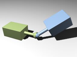
Ball joints provide a point around which the connected objects can rotate. Шаровые сочленения представляют собой точку, вокруг которой могут вращаться соединенные объекты.
|
|
|
Ball Joint
|
|
|
Ball Joint Parameters Параметры Ball Joint
|
The basic constraint parameters of this joint include: Основные параметры ограничения этого сочленения включают:
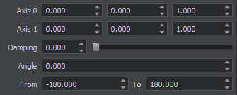
| Joint axis | Coordinates of the joint axis. Координаты оси сочленения. |
| Angular limit angle | Swing angle limit, specifies how much connected bodies can bend from the joint axis. Предел угла поворота, определяет, насколько соединенные тела могут изгибаться от оси соединения. |
| Angular limit from | Minimum angle in the range of twisting around the joint axis. The angle is specified in degrees in the [-180; 180] range. Минимальный угол в диапазоне скручивания вокруг оси сочленения. Угол указывается в градусах в диапазоне [ -180 ; 180 ]. |
| Angular limit to | Maximum angle in the range of twisting around the joint axis. The angle is specified in degrees in the [-180; 180] range. Максимальный угол в диапазоне скручивания вокруг оси сочленения. Угол указывается в градусах в диапазоне [ -180 ; 180 ]. |
This joint also has a set of common parameters shared by all joint types. Это сочленение также имеет набор общих параметров , общих для всех типов сочленений.
For more information refer to JointBall Class description. An example illustrating connection of two bodies using a ball joint can be found here. Дополнительные сведения см. в описании класса JointBall . Пример, иллюстрирующий соединение двух тел с помощью шарового сочленения, можно найти здесь .
Watch the illustration of the Ball joint settings in our video tutorial on physics. Посмотрите иллюстрацию настроек шарового сочленения в нашем видеоуроке по физике .
Prismatic JointPrismatic Joint#
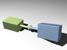
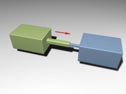
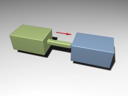
Prismatic joints allow movement along the joint axis. This joint has a linear motor attached. Призматические сочленения допускают движение вдоль оси шарнира. К этому сочленению прикреплен линейный мотор .
|
|
|
Prismatic Joint
|
|
|
Prismatic Joint Parameters Параметры Prismatic Joint
|
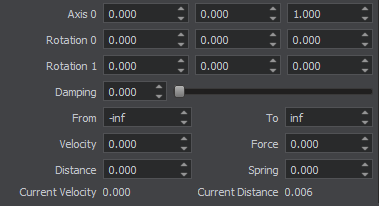
The basic constraint parameters of this joint include: Основные параметры ограничения этого сочленения включают:
| Joint axis | Coordinates of the joint axis. Координаты оси сочленения. |
| Linear damping | Linear damping coefficient of the prismatic joint. Линейный коэффициент демпфирования призматического сочленения. |
| Linear limit from | Minimum distance between the bodies along the joint axis. Минимальное расстояние между телами по оси сочленения. |
| Linear limit to | Maximum distance between the bodies along the joint axis. Максимальное расстояние между телами по оси сочленения. |
| Linear spring | Spring rigidity coefficient, determines how strong the joint resists linear motion. If rigidity is set to 0, the spring is disabled. Коэффициент жесткости пружины, определяет, насколько прочно сочленение сопротивляется линейному движению. Если жесткость установлена на 0 , пружина отключена. |
| Linear distance | Target linear distance of the attached spring. The spring (if it is enabled) tries to keep the specified distance between the connected bodies. Целевое линейное расстояние прикрепленной пружины. Пружина (если она включена) пытается сохранить заданное расстояние между соединенными телами. |
| Параметры двигателя | |
|---|---|
| Linear Force | Maximum force of the attached linear motor. 0 detaches the motor. Максимальное усилие присоединенного линейного двигателя. 0 отключает двигатель. |
| Linear Velocity | Target velocity of the attached linear motor. Целевая скорость присоединенного линейного двигателя. |
This joint also has a set of common parameters shared by all joint types. Это сочленение также имеет набор общих параметров , общих для всех типов сочленений.
For more information refer to JointPrismatic Class description. An example illustrating connection of two bodies using a prismatic joint can be found here. Для получения дополнительной информации см. описание JointPrismatic Class. Пример, иллюстрирующий соединение двух тел с помощью призматического сочленения, можно найти здесь .
Watch the illustration of the Prismatic joint in our video tutorial on physics. Посмотрите иллюстрацию призматического сочленения в нашем видеоуроке по физике .
Cylindrical JointCylindrical Joint#
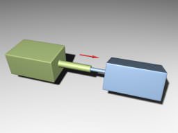
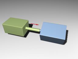
Cylindrical joints are like prismatic ones with an additional degree of freedom: rotation around the joint axis. This joint has a linear and an angular motors attached. Цилиндрические сочленения похожи на призматические с дополнительной степенью свободы: вращением вокруг оси сочленения. К этому сочленению прикреплены линейный и угловой моторы .
|
|
|
Cylindrical Joint
|
|
|
Cylindrical Joint Parameters Параметры Cylindrical Joint
|
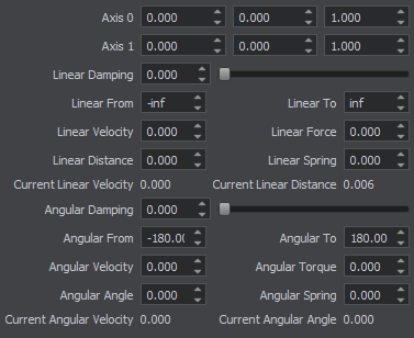
The basic constraint parameters of this joint include: Основные параметры ограничения этого сочленения включают:
| Joint axis | Coordinates of the joint axis. Координаты оси сочленения. |
| Linear damping | Linear damping coefficient of the cylindrical joint. Линейный коэффициент демпфирования цилиндрического сочленения. |
| Linear limit from | The minimum distance between the bodies along the joint axis. Минимальное расстояние между телами по оси сочленения. |
| Linear limit to | The maximum distance between the bodies along the joint axis. Максимальное расстояние между телами по оси сочленения. |
| Linear spring | Spring rigidity coefficient, determines how strong the joint resists linear motion. If rigidity is set to 0, the spring is disabled. Коэффициент жесткости пружины, определяет, насколько прочно сочленение сопротивляется линейному движению. Если жесткость установлена на 0 , пружина отключена. |
| Linear distance | A target linear distance of the attached spring. The spring (if it is enabled) tries to keep the specified distance between the connected bodies. Целевое линейное расстояние прикрепленной пружины. Пружина (если она включена) пытается сохранить заданное расстояние между соединенными телами. |
| Angular damping | Angular damping coefficient of the cylindrical joint. Угловой коэффициент демпфирования цилиндрического сочленения. |
| Angular limit from | The minimum angle in the range of twisting around the joint axis. The angle is specified in degrees in the [-180; 180] range. Минимальный угол в диапазоне скручивания вокруг оси сочленения. Угол указывается в градусах в диапазоне [ -180 ; 180 ]. |
| Angular limit to | The maximum angle in the range of twisting around the joint axis. The angle is specified in degrees in the [-180; 180] range. Максимальный угол в диапазоне скручивания вокруг оси сочленения. Угол указывается в градусах в диапазоне [ -180 ; 180 ]. |
| Angular spring | Spring rigidity coefficient, determines how strong the joint resists rotation. If rigidity is set to 0, the spring is disabled. Коэффициент жесткости пружины, определяет, насколько сильно сочленение сопротивляется вращению. Если жесткость установлена на 0 , пружина отключена. |
| Angular angle | A target angle of the attached angular spring. The spring (if it is enabled) tries to keep the specified angle between the connected bodies. Целевой угол прикрепленной угловой пружины. Пружина (если она включена) пытается сохранить заданный угол между соединенными телами. |
| Параметры двигателя | |
|---|---|
| Angular Torque | Maximum torque of the angular motor. 0 detaches the motor. Максимальный крутящий момент углового двигателя. 0 отключает двигатель. |
| Angular Velocity | Target velocity of the attached angular motor. Целевая скорость присоединенного углового двигателя. |
| Linear Force | Maximum force of the attached linear motor. 0 detaches the motor. Максимальное усилие присоединенного линейного двигателя. 0 отключает двигатель. |
| Linear Velocity | Target velocity of the attached linear motor. Целевая скорость присоединенного линейного двигателя. |
This joint also has a set of common parameters shared by all joint types. Это сочленение также имеет набор общих параметров , общих для всех типов сочленений.
For more information refer to JointCylindrical Class description. An example illustrating connection of two bodies using a cylindrical joint can be found here. Для получения дополнительной информации см. описание JointCylindrical Class. Пример, иллюстрирующий соединение двух тел с помощью цилиндрического сочленения, можно найти здесь .
Watch the illustration of the Cylindrical joint in our video tutorial on physics. Посмотрите иллюстрацию цилиндрического сочленения в нашем видеоуроке по физике .
Wheel JointWheel Joint#
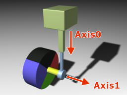
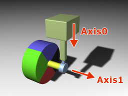
Wheel joints are used to create ray-cast vehicle wheels. It connects two rigid bodies: the first body is a frame, the second one is a wheel. There is no need to assign a shape to the wheel: ray casting is used to detect collision of the wheel with a surface. This joint has an angular motor attached. Wheel-сочленения используются для моделирования колес транспортных средств. Он соединяет два твердых тела : первое тело представляет собой кузов, второе - колесо. Присваивать форму (shape) колесу не нужно: для обнаружения столкновения колеса с поверхностью используется метод ray-casting. К этому сочленению прикреплен угловой мотор .
- If the bodies are connected using UnigineEditor:
- Select the vehicle frame.Select the vehicle frame.
- Add a wheel joint.Add a wheel joint.
- Specify the wheel to be attached.Specify the wheel to be attached.
- Select the vehicle frame.Select the vehicle frame.
- Add a wheel joint.Add a wheel joint.
- Specify the wheel to be attached.Specify the wheel to be attached.
- If the bodies are connected programmatically:
- b0 is a frame.b0 is a frame.
- b1 is a wheel.b1 is a wheel.
- b0 is a frame.b0 is a frame.
- b1 is a wheel.b1 is a wheel.
- Select the vehicle frame.Select the vehicle frame.
- Add a wheel joint.Add a wheel joint.
- Specify the wheel to be attached.Specify the wheel to be attached.
- b0 is a frame.b0 is a frame.
- b1 is a wheel.b1 is a wheel.
- If the bodies are connected using UnigineEditor:
- Select the vehicle frame.Select the vehicle frame.
- Add a wheel joint.Add a wheel joint.
- Specify the wheel to be attached.Specify the wheel to be attached.
- Select the vehicle frame. Выберите раму автомобиля.
- Add a wheel joint. Добавьте колесный шарнир.
- Specify the wheel to be attached. Укажите колесо, которое нужно прикрепить.
- If the bodies are connected programmatically:
- b0 is a frame.b0 is a frame.
- b1 is a wheel.b1 is a wheel.
- b0 is a frame. b0 is a frame.
- b1 is a wheel. b1 is a wheel.
|
|
Wheel Joint |
|
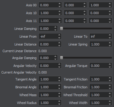
Wheel Joint Parameters Параметры Wheel Joint |
The basic constraint parameters of this joint include: Основные параметры ограничения этого сочленения включают:
| Suspension axis (Axis 0) Ось подвески (Axis 0) | Coordinates of a vertical axis, which acts like a cylindrical joint providing steering and damping. Координаты вертикальной оси, которая действует как цилиндрическое сочленение, обеспечивающее управление и демпфирование. |
| Wheel spindle axis (Axis 1) Ось шпинделя колеса (Axis 1) | Coordinates of a horizontal axis, around which the wheel rotates. They are set in the following fields:
|
| Linear damping | Linear damping coefficient of the suspension. Линейный коэффициент демпфирования подвески. |
| Linear limit from | Lower suspension ride limit. Нижний предел хода подвески. |
| Linear limit to | Upper suspension ride limit. Верхний предел хода подвески. |
| Linear spring | Suspension spring rigidity coefficient, determines how strong the joint resists vertical linear motion. If rigidity is set to 0, the spring is disabled. Коэффициент жесткости пружины подвески, определяет, насколько прочно соединение выдерживает вертикальное линейное движение. Если жесткость установлена на 0 , пружина отключена. |
| Linear distance | Target suspension height. The suspension spring (if it is enabled) tries to keep the specified height. Целевая высота подвески. Пружина подвески (если она включена) пытается сохранить заданную высоту. |
| Angular damping | Angular damping coefficient of wheel rotation. Угловой коэффициент демпфирования вращения колеса. |
| Параметры двигателя | |
|---|---|
| Angular Torque | Maximum torque of the angular motor. 0 detaches the motor. Максимальный крутящий момент углового двигателя. 0 отключает двигатель. |
| Angular Velocity | Target velocity of the attached angular motor. Целевая скорость присоединенного углового двигателя. |
This joint also has a set of common parameters shared by all joint types. Это сочленение также имеет набор общих параметров , общих для всех типов сочленений.
For more information refer to JointWheel Class description. For an example illustrating the use of wheel joints see the Creating a Car with Wheel Joints article. Для получения дополнительной информации см. описание JointWheel Class. Пример использования wheel-сочленения см. в статье Создание автомобиля с wheel-сочленениями .
Watch how to simulate a wheel using the Wheel joint in our video tutorial on physics. Посмотрите, как смоделировать колесо, используя соединение Wheel, в нашем видеоуроке по физике .
Suspension JointSuspension Joint#
Suspension joints are used to create wheel suspension for vehicles. It connects two rigid bodies: the first body is a frame, the second one is a wheel. This joint has an angular motor attached. Подвески используются для создания подвески колес автомобилей. Он соединяет два твердых тела : первое тело представляет собой раму, второе - колесо. К этому шарниру прикреплен угловой мотор .
- If the bodies are connected using UnigineEditor:
- Select the vehicle frame.Select the vehicle frame.
- Add a suspension joint.Add a suspension joint.
- Specify the wheel to be attached.Specify the wheel to be attached.
- Select the vehicle frame.Select the vehicle frame.
- Add a suspension joint.Add a suspension joint.
- Specify the wheel to be attached.Specify the wheel to be attached.
- If the bodies are connected programmatically:
- b0 is a frame.b0 is a frame.
- b1 is a wheel.b1 is a wheel.
- b0 is a frame.b0 is a frame.
- b1 is a wheel.b1 is a wheel.
- Select the vehicle frame.Select the vehicle frame.
- Add a suspension joint.Add a suspension joint.
- Specify the wheel to be attached.Specify the wheel to be attached.
- b0 is a frame.b0 is a frame.
- b1 is a wheel.b1 is a wheel.
- If the bodies are connected using UnigineEditor:
- Select the vehicle frame.Select the vehicle frame.
- Add a suspension joint.Add a suspension joint.
- Specify the wheel to be attached.Specify the wheel to be attached.
- Select the vehicle frame. Выберите раму автомобиля.
- Add a suspension joint. Добавьте suspension-сочленение.
- Specify the wheel to be attached. Укажите колесо, которое нужно прикрепить.
- If the bodies are connected programmatically:
- b0 is a frame.b0 is a frame.
- b1 is a wheel.b1 is a wheel.
- b0 is a frame. b0 is a frame.
- b1 is a wheel. b1 is a wheel.

|

|
|
Suspension Joint
|
|
|
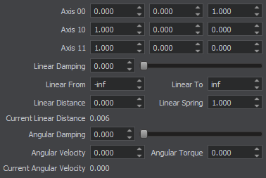
Suspension Joint Parameters Параметры Suspension Joint
|
The basic constraint parameters of this joint include: Основные параметры ограничения этого сочленения включают:
| Suspension axis (Axis 0) Ось подвески (Axis 0) | Coordinates of a vertical axis, which acts like a cylindrical joint providing steering and damping. Координаты вертикальной оси, которая действует как цилиндрическое сочленение, обеспечивающиее управление и демпфирование. |
| Wheel spindle axis (Axis 1) Ось шпинделя колеса (Axis 1) | Coordinates of a horizontal axis, around which the wheel rotates. They are set in the following fields:
|
| Linear damping | Linear damping coefficient of the suspension. Линейный коэффициент демпфирования подвески. |
| Linear limit from | Lower suspension ride limit. Нижний предел хода подвески. |
| Linear limit to | Upper suspension ride limit. Верхний предел хода подвески. |
| Linear spring | Suspension spring rigidity coefficient, determines how strong the joint resists vertical linear motion. If rigidity is set to 0, the spring is disabled. Коэффициент жесткости пружины подвески, определяет, насколько прочно сочленение выдерживает вертикальное линейное движение. Если жесткость установлена на 0 , пружина отключена. |
| Linear distance | Target suspension height. The suspension spring (if it is enabled) tries to keep the specified height. Целевая высота подвески. Пружина подвески (если она включена) пытается сохранить заданную высоту. |
| Angular damping | Angular damping coefficient of wheel rotation. Угловой коэффициент демпфирования вращения колеса. |
| Параметры двигателя | |
|---|---|
| Angular Torque | Maximum torque of the angular motor. 0 detaches the motor. Максимальный крутящий момент углового двигателя. 0 отключает двигатель. |
| Angular Velocity | Target velocity of the attached angular motor. Целевая скорость присоединенного углового двигателя. |
This joint also has a set of common parameters shared by all joint types. Это сочленение также имеет набор общих параметров , общих для всех типов сочленений.
For more information refer to JointSuspension Class description. An example illustrating connection of two bodies using a suspension joint can be found here. Для получения дополнительной информации см. описание JointSuspension Class. Пример, иллюстрирующий соединение двух кузовов с помощью шарнира подвески, можно найти здесь .
For the difference between the Suspension and Wheel joints, see our video tutorial on physics. Чтобы узнать о различиях между wheel- и suspension-сочленениями шарнирами, см. наш видеоурок по физике .
Path JointPath Joint#
Path joint is used to attach a rigid body to a path body and to make it move along this path. This joint can be used to make a train move along the tracks. This joint has a linear motor attached. Path-сочленение используется для прикрепления твердого тела (rigid) к path-телу и для его перемещения по этому пути. Это сочленение можно использовать для движения поезда по рельсам. К этому сочленению прикреплен линейный мотор .
The order of the bodies, connected using a path joint, matters!
- If the bodies are connected using UnigineEditor:
- Select a rigid body.Select a rigid body.
- Add a path joint.Add a path joint.
- Specify the path body.Specify the path body.
- Select a rigid body.Select a rigid body.
- Add a path joint.Add a path joint.
- Specify the path body.Specify the path body.
- If the bodies are connected programmatically:
- b0 is a BodyRigid.b0 is a BodyRigid.
- b1 is a BodyPath.b1 is a BodyPath.
- b0 is a BodyRigid.b0 is a BodyRigid.
- b1 is a BodyPath.b1 is a BodyPath.
- Select a rigid body.Select a rigid body.
- Add a path joint.Add a path joint.
- Specify the path body.Specify the path body.
- b0 is a BodyRigid.b0 is a BodyRigid.
- b1 is a BodyPath.b1 is a BodyPath.
The order of the bodies, connected using a path joint, matters!
- If the bodies are connected using UnigineEditor:
- Select a rigid body.Select a rigid body.
- Add a path joint.Add a path joint.
- Specify the path body.Specify the path body.
- Select a rigid body. Выберите твердое тело (rigid).
- Add a path joint. Добавить path-сочленение.
- Specify the path body. Укажите path-тело.
- If the bodies are connected programmatically:
- b0 is a BodyRigid.b0 is a BodyRigid.
- b1 is a BodyPath.b1 is a BodyPath.
- b0 is a BodyRigid. b0 - это BodyRigid.
- b1 is a BodyPath. b1 - это BodyPath.
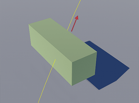
|
|
Path Joint
|

|
|
Path Joint Parameters Параметры Path Joint
|
The basic constraint parameters of this joint include: Основные параметры ограничения этого сочленения включают:
| Rotation | Specifies orientation of the body relative to the path. Задает ориентацию тела относительно пути. |
| Linear damping | Linear damping coefficient of the path joint. Линейный коэффициент демпфирования path-сочленения. |
| Параметры двигателя | |
|---|---|
| Linear Force | Maximum force of the attached linear motor. 0 detaches the motor. Максимальное усилие присоединенного линейного двигателя. 0 отключает двигатель. |
| Linear Velocity | Target velocity of the attached linear motor. Целевая скорость присоединенного линейного двигателя. |
This joint also has a set of common parameters shared by all joint types. Это сочленение также имеет набор общих параметров , общих для всех типов сочленений.
For more information refer to JointPath Class description. An example illustrating connection of two bodies using a path joint can be found here. Для получения дополнительной информации см. описание JointPath Class. Пример, иллюстрирующий соединение двух тел с помощью path-сочленения, можно найти здесь .
Our video tutorial on physics shows how to attach a rigid body to a path body using the Path joint. В нашем видеоуроке по физике показано, как прикрепить rigid-тело к path-телу с помощью path-сочленения.
Particles JointParticles Joint#
Particles joint is used to pin cloth body or rope body to a rigid body, ragdoll body or a dummy body. Particles-сочленение используется для прикрепления ткани или веревки к твердому телу , ragdoll-телу или dummy-телу .
- If the bodies are connected using UnigineEditor:
- Select a rigid body, a ragdoll body or a dummy body.Select a rigid body, a ragdoll body or a dummy body.
- Add a particles joint.Add a particles joint.
- Specify a cloth body or a rope body.Specify a cloth body or a rope body.
- Select a rigid body, a ragdoll body or a dummy body.Select a rigid body, a ragdoll body or a dummy body.
- Add a particles joint.Add a particles joint.
- Specify a cloth body or a rope body.Specify a cloth body or a rope body.
- If the bodies are connected programmatically:
- b0 is a BodyRigid / BodyRagdoll / BodyDummy.b0 is a BodyRigid / BodyRagdoll / BodyDummy.
- b1 is a BodyCloth / BodyRope.b1 is a BodyCloth / BodyRope.
- b0 is a BodyRigid / BodyRagdoll / BodyDummy.b0 is a BodyRigid / BodyRagdoll / BodyDummy.
- b1 is a BodyCloth / BodyRope.b1 is a BodyCloth / BodyRope.
- Select a rigid body, a ragdoll body or a dummy body.Select a rigid body, a ragdoll body or a dummy body.
- Add a particles joint.Add a particles joint.
- Specify a cloth body or a rope body.Specify a cloth body or a rope body.
- b0 is a BodyRigid / BodyRagdoll / BodyDummy.b0 is a BodyRigid / BodyRagdoll / BodyDummy.
- b1 is a BodyCloth / BodyRope.b1 is a BodyCloth / BodyRope.
- If the bodies are connected using UnigineEditor:
- Select a rigid body, a ragdoll body or a dummy body.Select a rigid body, a ragdoll body or a dummy body.
- Add a particles joint.Add a particles joint.
- Specify a cloth body or a rope body.Specify a cloth body or a rope body.
- Select a rigid body, a ragdoll body or a dummy body. Выберите твердое тело, ragdoll- или dummy-тело.
- Add a particles joint. Добавьте соединение частиц.
- Specify a cloth body or a rope body. Укажите тело ткани (cloth) или тело веревки (веревки).
- If the bodies are connected programmatically:
- b0 is a BodyRigid / BodyRagdoll / BodyDummy.b0 is a BodyRigid / BodyRagdoll / BodyDummy.
- b1 is a BodyCloth / BodyRope.b1 is a BodyCloth / BodyRope.
- b0 is a BodyRigid / BodyRagdoll / BodyDummy. b0 - это BodyRigid / BodyRagdoll / BodyDummy.
- b1 is a BodyCloth / BodyRope. b1 - это BodyCloth / BodyRope.

|
|
Particles Joint
|

|
|
Particles Joint Parameters Параметры Particles Joint
|
The basic constraint parameters of this joint include: Основные параметры ограничения этого сочленения включают:
| Threshold | Determines the distance for pinning vertices of cloth or rope body to another body. Определяет расстояние для прикрепления вершин ткани или веревки к другому телу. |
| Size | Specifies the area for pinning vertices of cloth or rope body to another body. Определяет область для закрепления вершин ткани или веревки на другом теле. |
This joint also has a set of common parameters shared by all joint types. Это сочленение также имеет набор общих параметров , общих для всех типов сочленений.
For more information refer to JointParticles Class description. An example illustrating attachment of a cloth body using a particles joint can be found here. Для получения дополнительной информации см. описание JointParticles Class. Пример, иллюстрирующий прикрепление тканевого тела с помощью соединения частиц, можно найти здесь .
An example illustrating the use of rope body and particles joint can be found here. Пример, иллюстрирующий использование веревки и particles-сочленения, можно найти здесь .
Our video tutorial on physics shows how to attach a rope or a cloth to other bodies using the Particles joint. В нашем видеоуроке по физике показано, как прикрепить веревку или ткань к другим телам с помощью particles-сочленения.
Common Joint ParametersОбщие параметры соединения#
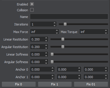
|
|
Common Joint Parameters Общие параметры сочленений
|
All joints regardless of their type have some common parameters: Все сочленения, независимо от их типа, имеют некоторые общие параметры:
| Enabled | A flag indicating if a joint is enabled. Флаг, указывающий, включено ли сочленение. |
| Collision | A flag indicating if collision detection between the connected bodies is enabled. Флаг, указывающий, включено ли обнаружение столкновений между соединенными телами. |
| Anchor | Position of the anchor point around which the joint's motion is constrained. By default the anchor is placed between the centers of mass of connected bodies. Положение точки привязки, вокруг которой ограничено движение сочленения. По умолчанию якорь размещается между центрами масс соединенных тел. |
| Linear restitution | Linear stiffness of the joint. Defines how fast it compensates for linear coordinate change between two bodies. When bodies are dragged apart, restitution controls the magnitude of force which is applied to both bodies so that their anchor points to become aligned again.
Примечание
1 means that the joint is to return bodies in place throughout 1 physics tick.0.2 means that the joint is to return bodies in place throughout 5 physics ticks.The maximum value of 1 can lead to destabilization of physics (as too great forces are applied).Линейная жесткость сочленения. Определяет, насколько быстро он компенсирует линейное изменение координат между двумя телами. Когда тела тянутся друг от друга, восстановление управляет величиной силы, которая применяется к обоим телам, чтобы их опорные точки снова выровнялись.
The maximum value of 1 can lead to destabilization of physics (as too great forces are applied).The maximum value of 1 can lead to destabilization of physics (as too great forces are applied).
Примечание
The maximum value of 1 can lead to destabilization of physics (as too great forces are applied). Максимальное значение 1 может привести к дестабилизации физики (поскольку прилагаются слишком большие силы). |
| Angular restitution | Angular stiffness of the joint. Defines how fast it compensates for change of the angle between two bodies. When bodies are turned relative each other, restitution controls the magnitude of force which is applied to both bodies so that their anchor points to become aligned again.
Примечание
1 means that the joint is to return bodies in place throughout 1 physics tick.0.2 means that the joint is to return bodies in place throughout 5 physics ticks.The maximum value of 1 can lead to destabilization of physics (as too great forces are applied).Угловая жесткость сочленения. Определяет, насколько быстро он компенсирует изменение угла между двумя телами. Когда тела поворачиваются относительно друг друга, восстановление управляет величиной силы, которая применяется к обоим телам, так что их опорные точки снова выравниваются.
The maximum value of 1 can lead to destabilization of physics (as too great forces are applied).The maximum value of 1 can lead to destabilization of physics (as too great forces are applied).
Примечание
The maximum value of 1 can lead to destabilization of physics (as too great forces are applied). Максимальное значение 1 может привести к дестабилизации физики (поскольку прилагаются слишком большие силы). |
| Linear softness | Linear elasticity of the joint. Defines whether linear velocities of the bodies are averaged out when the joint is stretched.
|
| Angular softness | Angular elasticity of the joint. Defines whether linear velocities of the bodies are averaged out when the joint is twisted.
|
| Max force | Maximum force that can be exerted on the joint. If this limit is exceeded, the joint breaks. The default value is inf, i.e. the joint is unbreakable. Максимальное усилие, которое можно приложить к сочленению. Если этот предел превышен, сочленение разрывается. Значение по умолчанию - inf , т.е. сочленение неразрывно. |
| Max torque | Maximum torque that can be exerted on the joint. If this limit is exceeded, the joint breaks. The default value is inf, i.e. the joint is unbreakable. Максимальный крутящий момент, который можно приложить к сочленению. Если этот предел превышен, сочленение разрывается. Значение по умолчанию - inf , т.е. сочленение неразрывно. |
| Number of iterations | Joints, like collisions, are calculated iteratively. This parameter specifies the number of iterations used to solve joints. Note that if this value is too low, the precision of calculations will suffer. Сочленения, как и столкновения, рассчитываются итеративно. Этот параметр указывает количество итераций, используемых для решения сочленений. Обратите внимание: если это значение будет слишком низким, пострадает точность вычислений. |
Motors and SpringsДвигатели и пружины#
Joints can have motors and springs associated with them. Сочленения могут иметь двигатели и связанные с ними пружины.
Springs try to keep the bodies connected with a joint at some specific distance (linear) or angle (angular). The behavior of a particular spring depends on its rigidity and damping coefficient. Пружины пытаются удерживать тела, соединенные сочленением, на определенном расстоянии (линейном) или под углом (угловой). Поведение конкретной пружины зависит от ее жесткости и коэффициента демпфирования.
Motors provide movement or rotation of bodies connected with a joint relative to each other by applying a torque (or force) to a joint's degree of freedom. There are linear and angular motors that exert a limited force to a joint, pushing or rotating connected objects. Двигатели обеспечивают движение или вращение тел, связанных с шарниром, относительно друг друга за счет приложения крутящего момента (или силы) к степени свободы сочленения. Существуют линейные и угловые двигатели, которые оказывают ограниченное усилие на сочленение, толкая или вращая связанные объекты.
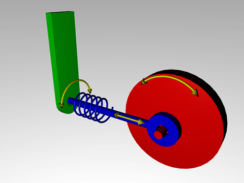
Motors have two parameters: У двигателей есть два параметра:
- Target velocity
- Maximum force (or torque) that is available to reach that velocity. Maximum force (или крутящий момент), который доступен для достижения этой скорости.
This is a very simple model of real life motors. However, is it quite useful when modeling a motor, that is geared down with a gearbox before being connected to the joint. Such devices are often controlled by setting a target velocity, and can only generate a maximum amount of power to achieve that speed (which corresponds to a certain amount of force available at the joint). Это очень простая модель реальных двигателей. Тем не менее, это очень полезно при моделировании двигателя, который перед подсоединением к сочленению приводится в действие редуктором. Такие устройства часто управляются путем установки целевой скорости и могут генерировать только максимальное количество энергии для достижения этой скорости (что соответствует определенному количеству силы, доступной в сочленении).
To activate an angular motor perform the following steps: Чтобы активировать угловой двигатель , выполните следующие действия:
- Set angular velocity - target angular velocity of the motor, This value determines how fast the motor can rotate.
- positive value - the motor rotates counterclockwise.positive value - the motor rotates counterclockwise.
- negative value - the motor rotates clockwise.negative value - the motor rotates clockwise.
- positive value - the motor rotates counterclockwise. положительное значение - двигатель вращается против часовой стрелки.
- negative value - the motor rotates clockwise. отрицательное значение - двигатель вращается по часовой стрелке.
- Set angular torque - maximum torque applied by the motor to reach target velocity. This value determines how fast the motor reaches maximum velocity.
- 0 disables the motor.0 disables the motor.
- If a negative value is provided, 0 will be used instead.If a negative value is provided, 0 will be used instead.
- 0 disables the motor. 0 отключает двигатель.
- If a negative value is provided, 0 will be used instead. Если указано отрицательное значение, вместо него будет использоваться 0 .
To activate a linear motor perform the following steps: Чтобы активировать линейный двигатель , выполните следующие действия:
- Set linear velocity - target linear velocity of the motor, This value determines how fast the motor can push.
- positive value - the motor pushes forward.positive value - the motor pushes forward.
- negative value - the motor pulls backward.negative value - the motor pulls backward.
- positive value - the motor pushes forward. положительное значение - двигатель толкает вперед.
- negative value - the motor pulls backward. отрицательное значение - двигатель движется назад.
- Set linear force - maximum force applied by the motor to reach target velocity. This value determines how fast the motor reaches maximum velocity.
- 0 disables the motor.0 disables the motor.
- If a negative value is provided, 0 will be used instead.If a negative value is provided, 0 will be used instead.
- 0 disables the motor. 0 отключает двигатель.
- If a negative value is provided, 0 will be used instead. Если указано отрицательное значение, вместо него будет использоваться 0 .
VehiclesТранспортные средства#
Vehicles are important in real-time games, therefore, they are to be described separately. There are two approaches to simulation of moving vehicles. Each approach has a corresponding joint type to connect wheels to vehicle body. Транспортные средства важны в играх в реальном времени, поэтому их следует описывать отдельно. Есть два подхода к моделированию движущихся транспортных средств. У каждого подхода есть соответствующий тип соединения для соединения колес с кузовом автомобиля.
- The first approach uses a suspension joint and assumes that wheels are represented as physical bodies with shapes. As each wheel has a collider shape, collisions with objects on the ground are handled correctly. For example, such car runs on a curb smoothly. This approach requires more calculations and is to be used when more accurate simulation is needed especially for step-like ground surface and wheels have a complex shape. Первый подход использует suspension joint и предполагает, что колеса представлены как физические тела с формами (shapes). Поскольку каждое колесо имеет форму коллайдера, столкновения с объектами на земле обрабатываются правильно. Например, такая машина плавно едет по бордюру. Этот подход требует дополнительных расчетов и должен использоваться, когда требуется более точное моделирование, особенно для ступенчатой поверхности земли и колес сложной формы.
- The second approach uses a wheel joint and assumes that the wheels are virtual. Wheels do not collide with the surface of the road. Instead, rays are cast down from the car body to detect surface unevenness. In this case steep changes of the terrain are not handled accurately. This approach is faster then the first one and provides acceptable results for smooth terrain, e.g. for racing cars simulation. However, on cross-country terrains it may not work correctly. Второй подход использует wheel joint и предполагает, что колеса виртуальные. Колеса не сталкиваются с поверхностью дороги. Вместо этого лучи падают от кузова автомобиля, чтобы обнаружить неровности поверхности. В этом случае резкие изменения рельефа обрабатываются неточно. Этот подход быстрее первого и обеспечивает приемлемые результаты для ровной местности, например для моделирования гоночных автомобилей. Однако на пересеченной местности он может работать некорректно.
Both joints have a motor associated with them, which rotates the wheels and pushes the vehicle forward. Оба сочленения имеют связанный с ними мотор , который вращает колеса и толкает автомобиль вперед.
