Global Terrain
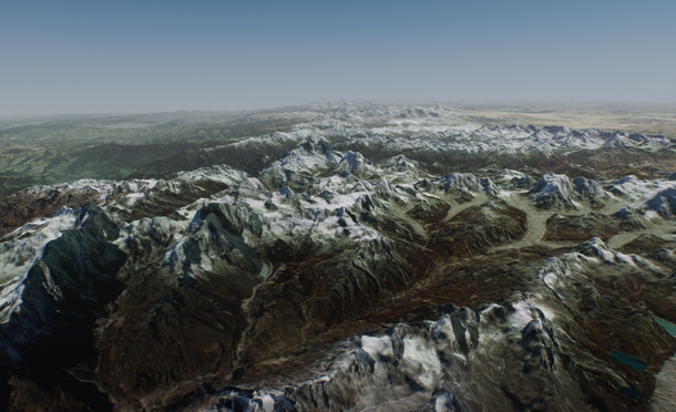
Global Terrain is a virtually limitless terrain representing a certain fragment of the Earth's surface. It can be generated on the basis of ordinary raster images and/or GIS data. In case of using GIS data, the appearance of the Global Terrain object is determined by the accuracy and availability of geospatial data. It should be noted that there are areas of the Earth's surface with only low-resolution data available or even no geospatial data at all.
This type of terrain can be successfully used for flight simulators: most of the time the plane remains at a very high altitude and low-resolution data is sufficient. High-resolution data is necessary only around landing and take-off areas.
- There can be only one Global Terrain object on the scene.
- Memory consumption increases significantly when several viewports are used.
See Also#
- The terrain_global_base material
- The Global Terrain Details article to learn more about setting up visual representation of the global terrain
- The Sandworm tool article to learn about Global Terrain generation
- The ObjectTerrainGlobal class to edit Global Terrain via API
- The Tileset class to manage tileset data of Global Terrain via API
- The TilesetFile class to manage tileset files of the Global Terrain via API
Terrain Structure#
Global Terrain is represented by the following data layers:
- Height data generated on the basis of GIS elevation data or height maps (if non-georeferenced data is used for terrain generation).
- Albedo data generated on the basis of GIS satellite imagery data or albedo textures (if non-georeferenced data is used for terrain generation).
- Normal data generated on the basis of height data.
- Masks data generated on the basis of landcover data.
Tiling#
Global Terrain has a regular grid and is represented as a tileset. Each tile has a fixed size of 128 x 128 pixels. The number of tiles in each dimension (X and Y) is determined by the area size and data density. The higher the density the more tiles will be generated for the corresponding tileset.
For example, we have a height data texture with the density of 100 meters per pixel for an area of 50 square kilometers. Thus, we need (50000/100) x (50000/100) = 500 x 500 pixels which can be covered by 4 x 4 tiles.
Terrain tiles are stored on disk using a special format. The number of tiles, that can be stored on a disk is limited only to its capacity.
At run time, the tiles around the viewpoint are automatically loaded to GPU memory according to visibility distances specified for corresponding LODs. These visibility distances determine the number of tiles to be loaded and can be automatically reduced by the Engine in case if a GPU memory limit was reached.
Visible tiles change as the viewpoint moves along the terrain.
LODs#
A level of detail (LOD) system automatically adapts the available resolution of terrain grid according to the distance and loads corresponding tiles.
Every particular data layer has its own number of LODs. Each LOD of a particular data layer is represented by a separate tileset and has a number of parameters according to data layer type. Each LOD has its own density (in meters per pixel) which determines the size of its tileset. The higher the LOD density, the bigger the LOD tileset (the density is multiplied by the size of a single tile).
LODs are loaded and cleared in accordance with corresponding distances specified in the Node tab. These distances are to be used to avoid delays and provide smoothness when switching between LODs as well as to ensure efficient memory use.
Resolution and visibility distance together determine the number of tiles to be loaded around the viewpoint.
Blending of LODs#
As it was mentioned, there might be no data available for a more detailed LOD of a certain area. In this case the values of the two adjacent LODs are blended together to provide a smooth look without sharp edges or black holes. Blending is performed by means of linear interpolation on the basis of masks generated by the Sandworm Tool for a certain tile.
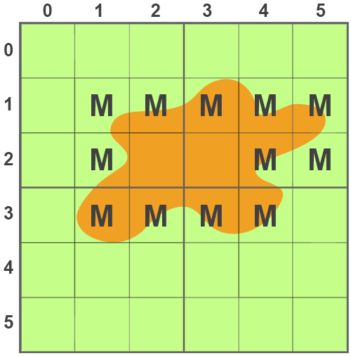
Let us consider the following example. Suppose we have two LODs:
- LOD1 with the resolution of 100 meters per pixel — green area
- LOD0 with the resolution of 30 meters per pixel — orange area
In this case masks are generated only for the tiles marked with M.
Creating a Global Terrain#
You can only create a Global Terrain object using the Sandworm Tool.
Please refer to the Sandworm article to learn more about terrain generation in the Sandworm Tool.
Terrain Parameters#
The Global Terrain parameters can be adjusted on the terrain's Node tab in the Parameters window. Each data layer contains a list of LODs with corresponding parameters.
Height Data#
Parameters of a certain LOD of the height data layer can be accessed via the LODs section of the Node tab in the Parameters window.
You can add a new height or remove an existing one by clicking  or
or  respectively. Added heights can be toggled on and off by using checkboxes inside the Height window.
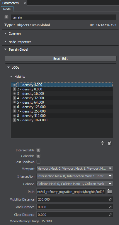
The following parameters are available for the Height LODs:
- Intersectable — toggle intersection detection for the current height LOD on and off.
- Collidable — toggle collision detection for the current height LOD on and off.
Cast Shadow — toggle shadow casting for the current height LOD on and off. You can use this parameter for performance optimization: disable shadow casting for high-poly LODs and enable for low-poly ones.
NoticeWhen only the low-poly LOD casts shadows, the high-poly LOD may be shadowed in areas where it shouldn't be. To reduce this effect, use the Shadow Offset parameter of the terrain material.- Viewport — viewport mask for the current height LOD.
- Intersection — intersection mask for the current height LOD.
- Collision — collision mask for the current height LOD.
- Path — path to a folder, in which the current height LOD is stored.
- Visibility distance — the distance starting from which the tiles of the current height LOD become visible.
- Load distance — the distance starting from which the tiles of the current height LOD are loaded into memory.
- Clear distance — the distance starting from which the tiles of the current height LOD are removed from memory.
- Video memory usage — memory consumption of the current height LOD.
Albedo Data#
Parameters of a certain LOD of the albedo data layer can be accessed via the Albedo section of the Node tab in the Parameters window.
You can add a new LOD or remove an existing one by clicking or respectively. Added albedo layers can be toggled on and off by using checkboxes inside the Albedo window.
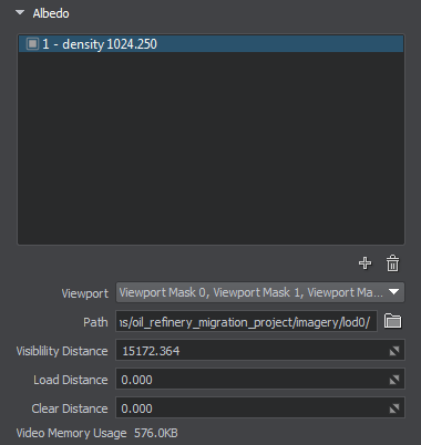
The following parameters are available for the Albedo LODs:
- Viewport — viewport mask for the current albedo LOD.
- Path — path to a folder, in which the current albedo LOD is stored.
- Visibility Distance — the distance starting from which the tiles of the current albedo LOD become visible.
- Load Distance — the distance starting from which the tiles of the current albedo LOD are loaded into memory.
- Clear Distance — the distance starting from which the tiles of the current albedo LOD are removed from memory.
- Video Memory Usage — memory consumption of the current albedo LOD.
Normal Data#
Parameters of a certain LOD of the normal data layer can be accessed via the Normals section of the Node tab in the Parameters window.
You can add a new LOD or remove an existing one by clicking or respectively. Added normal layers can be toggled on and off by using checkboxes inside the Normals window.
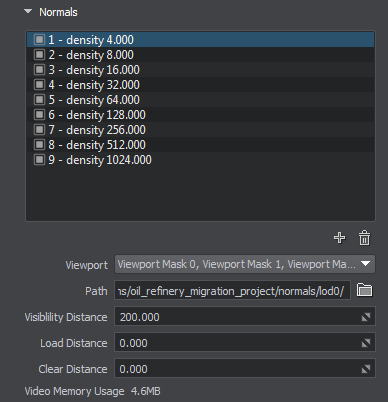
The following parameters are available for the Normal LODs:
- Viewport — viewport mask for the current normal LOD.
- Path — path to a folder, in which the current normal LOD is stored.
- Visibility Distance — the distance starting from which the tiles of the current normal LOD become visible.
- Load Distance — the distance starting from which the tiles of the current normal LOD are loaded into memory.
- Clear Distance — the distance starting from which the tiles of the current normal LOD are removed from memory.
- Video Memory Usage — memory consumption of the current normal LOD.
Masks Data#
Parameters of a certain LOD of the masks data layer can be accessed via the Mask section of the Node tab in the Parameters window.
You can add a new LOD or remove an existing one by clicking or respectively. Added mask layers can be toggled on and off by using checkboxes inside the Mask window.
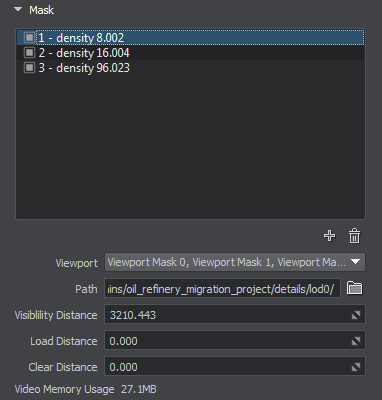
The following parameters are available for the Mask LODs:
- Viewport — viewport mask for the current masks LOD.
- Path — path to a folder, in which the current masks LOD is stored.
- Visibility Distance — the distance starting from which the tiles of the current masks LOD become visible.
- Load Distance — the distance starting from which the tiles of the current masks LOD are loaded into memory.
- Clear Distance — the distance starting from which the tiles of the current masks LOD are removed from memory.
- Video Memory Usage — memory consumption of the current masks LOD.
Terrain Data Storage Format#
Generated terrain data is stored in the specified folder with the following structure:
 detail masks
- heights
- imagery
- normals
- landcover masks for each type of generated landcover objects stored in separate folders with the corresponding names.
- vector_data masks for each type of generated vector objects stored in separate folders with the corresponding names.

Editing a Global Terrain#
You can edit any height, albedo or mask LOD of the Global Terrain object using the Terrain Editor tool.
To start editing the current terrain, click Brush Edit in the Terrain Global section of the Node tab in the Parameters window.
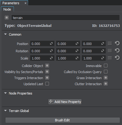
The Terrain Editor window will be displayed.

When you're done editing the terrain, click either Apply to apply all changes and exit the terrain editor, or Cancel to discard your changes.
Please refer to the Editing Global Terrain article to learn more about manual terrain modification with brushes.
Global Terrain Physics Simulation#
The terrain takes part in physics simulation if it has a standard surface_base property assigned. Collisions with physical bodies use the most detailed LOD 0 and are handled within a set distance, where simulation of physics is in effect.
Physical interaction can also be enabled for each of the height LODs by setting collision and intersection flags and masks.
Collisions are calculated for untessellated terrain geometry which may differ from the rendered geometry that is seen. Thus, in certain cases objects may seem "flying" above the terrain surface.
Planar Reflections and Oblique Frustum#
Some performance optimizations of the Global Terrain object, such as oblique frustum and backface culling, may lead to graphic artefacts in case if planar reflections or oblique frustum are used with a low-poly terrain.
In case of excessive culling, when too many polygons are removed (e.g., can be noticed in incorrect water reflections of the terrain), it is recommended to reduce the values of Oblique Frustum Culling and Back Face Culling parameters of the terrain_global_base material.
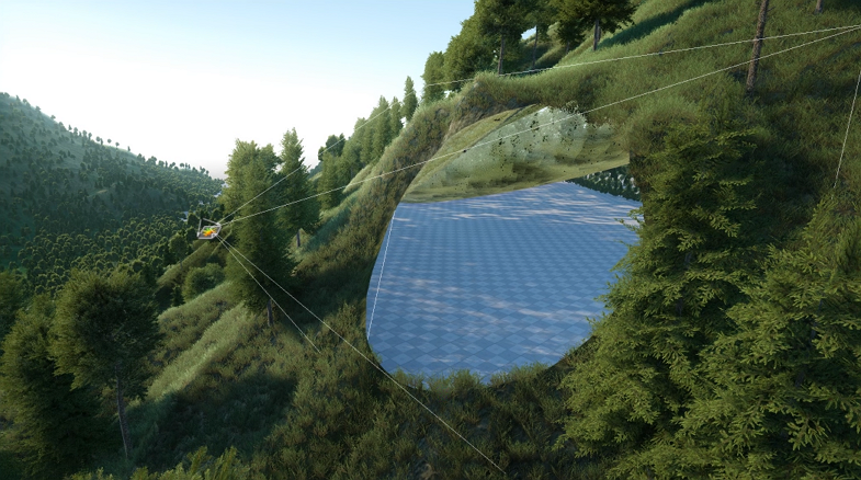
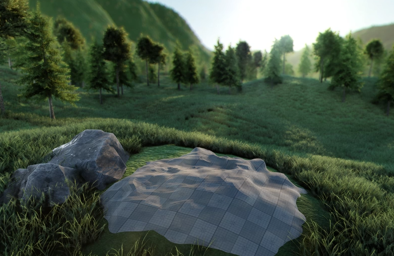
Creating Decal-Based Holes#
In some cases you may need to cut out an area of the terrain surface. For this purpose the Decal-Based Holes feature is supported by Global Terrain.
Place any decal (orthographic, projected or a mesh one) with the decal_terrain_hole_base material assigned over the desired location.
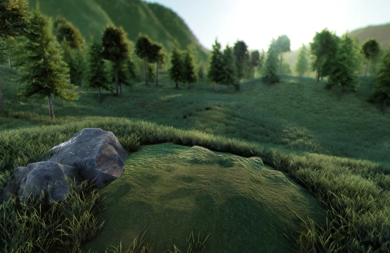
This will create a hole in the terrain surface.
Accurate intersection with decal-based terrain holes is supported, enabling collision detection as well as all corresponding Editor features such as selection, snapping to surface, etc.
Customizing Terrain Surface#
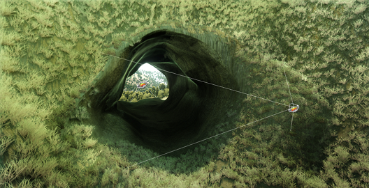
You can improve the landscape by integrating complex meshes into it and thus creating more detailed areas than the Global Terrain is able to provide due to limited density.
Enabled Terrain Lerp state of the mesh_base material marks an object to be covered by projected textures of the Global Terrain.
The feature is suitable for creating any insets such as caves and tunnels through mountains on the terrain. As an example, on the picture below a tunnel is integrated by just cutting some area of the terrain with a decal and replacing it with a mesh with the Terrain Lerp parameter enabled.
The information on this page is valid for UNIGINE 2.20 SDK.