Configuring Projections
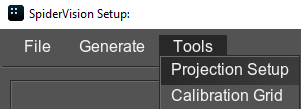
To set up projections, select Tools -> Projection Setup in the SpiderVision Setup window menu:
The Projection Setup window will open. This window makes it possible to:
- Rotate and flip projections.
- Control warping for each projection.
- Set up edge blending and masks for each projection.
- Correct color intensity for each projection.
Common Settings#
These settings are common for most tabs of Projection Setup:
| Current Viewport | Select a projection in the drop-down list to set up its parameters. You can also use Page Up and Page Down buttons to switch between projections. |
|---|---|
| Apply | Enables or disables application of the selected projection setting to the rendered image in the current viewport. |
| Help |
Displays the window with the information on controls that may be used in the grid area:
|
 |
The button to undo all panning and zooming actions and make the grid fit the window. |
| Shift Step | Step to shift the selected points with arrow keys. Use + to increase the value, or - to decrease it. |
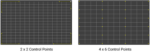
| Resolution |
The number of control points along the horizontal and vertical axes of the grid. A 2 x 2 grid is used by default.
Notice
The maximum grid size is 32 x 32. For Blend Zones, this setting controls the number of horizontal lines only. |
| Point | Horizontal and vertical indices of the selected control point. Enumeration starts from the bottom left corner. |
| Position |
Coordinates of the selected control point along the X and Y axes.
Coordinates for control points
|
| Type |
Type of line curving for the selected control point:
|

 — non-controllable linear handles with the offset equal to 0
 — controllable smooth handles with transversely aligned offsets
 — controllable break handles with individually configurable offsets
 — non-controllable handles with the automatically calculated offsets
Warping#

The Warp tab allows you to set up geometry correction for your projections. Areas where geometry correction is required include:
- Advanced off-axis correction where projector placement is awkward and needs an advanced mapping over the keystone function in a projector
- Non-planar screens such a curved screens and hemispherical domes
- Projecting one image from one projector onto more than one surface
- Unusual projection applications onto custom designed screens
Warping is performed by modifying the displayed grid in the visual editor. Set up warping for the selected projection using control points and yellow handles. These handles are displayed for each selected control point depending on its type.
The possible ways of controlling the point positions are listed here.
You can see an example of a warped grid and a corresponding projection image below.


In addition to the common settings, the following options specific for the Warp tab are available:
| Reset Warp Grid | Resets the warp grid to the default state. |
|---|---|
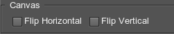
| Canvas |
Configure the canvas for the selected projection: enable vertical and horizontal flipping.
|
Color and Brightness Correction#
The Color Correction tab allows you to correct color intensity, as well as to adjust color balance for the selected projection.
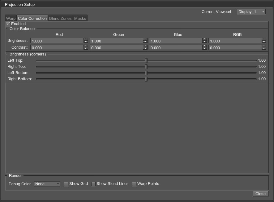


All Color Balance parameters can be reset to defaults by clicking the corresponding parameter name (by line or by column).

Blending#
The Blend Zones tab allows you to configure blending in the selected area.
The screen-space blend area is not affected by warping.
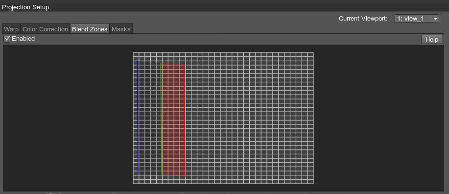
To start creating the blending area, click the Add button, and in the grid, click to define one side of the area, then click to define the other side — the green line will appear. The third click shows the blending direction.
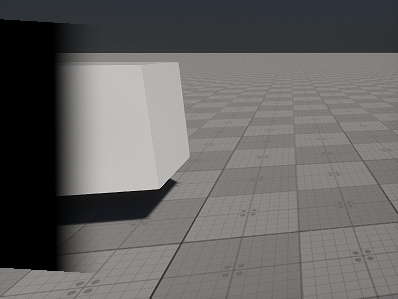
The area of the screen-space blend area is divided into two parts: the part between the blue and green lines is a solid-black area (i.e. the projected image is not displayed at all), and the part between the green and red lines is a gradient area (i.e. the projected image gradually becomes transparent).
In plain words, if you have two projectors, the green line of the blend zone in one projection should coincide with the red line of the blend zone in the other projection. For more than two projectors, the area between blue and green lines is used.
By default, each of these lines has two points marking the line limits. Using Resolution, you can increase the number of points along each line to adjust it as required by moving the points. Multi-selection of points is available.
In addition to the common settings, the following options specific for the Blend Zones tab are available:
Masking#
The Masks tab allows using masks to cut out certain areas of the selected projection.
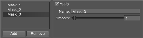
To create a mask, click Add and ensure that the Creation Mode button is enabled. Then create at least three points on the grid by clicking in the required place. The corresponding area of the projection will be cut out. The list of masks for the current projection is displayed under the grid. You can add new masks and remove existing ones using the corresponding buttons.
To add new points to the mask selected in the list, ensure that the Creation Mode button is enabled. Then you can add new points by clicking within the grid area. To insert a new point into an existing mask, select the point next to which a new point is to be added, and click to insert a new one. You can drag an existing point to move it. To remove a point, right-click it.
As you select a mask in the list, its parameters are displayed on the panel next to it:
Render#
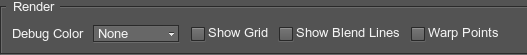
The Render block of settings is located at the bottom of the Projection Setup window. These settings are designed to facilitate fine-tuning of the projection by displaying the auxiliary elements on the actual projection.
| Debug Color | Temporarily set individual colors for different projections. This helps to visualize overlapping regions. |
|---|---|
| Show Grid | Display the warp grid in the viewport. |
| Show Warp Points | Display the selected warp points and auxiliary lines showing the point location (useful if the point is outside the projection boundaries). |
| Show Blend Points | Display blend zones with selected points and auxiliary lines showing the point location (useful if the point is outside the projection boundaries). The red and green lines marking the blend zone are used for correct mapping of overlapping projections. |
The information on this page is valid for UNIGINE 2.20 SDK.