Geodetic Pivot
A Geodetic Pivot object is an abstract object that contains an ellipsoid with a pivot point. By using Geodetic Pivot you can place objects on the scene on the corresponding places in the real world.
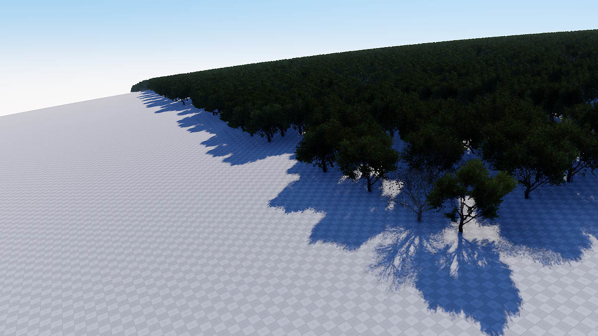
Geodetic Pivot helps to place world objects on their real world positions (latitude, longitude and altitude) by curving a plane with objects on it. Pivot converts real geodetic data to Cartesian and simultaneously "curves" objects to simulate the contorted Earth's surface.
Geodetic Pivot works with:
- ObjectTerrainGlobal
- ObjectWaterGlobal
- ObjectCloudLayer
- ObjectSky
- ObjectMeshStatic
- ObjectGrass
- ObjectMeshClutter
- WorldClutter
- Mesh Decals
See Also#
- The GeodeticPivot class to manage scenes with geodetic data via API
- The render_show_geodetic_pivot console command to show Geodetic Pivots in the scene
- A Wikipedia article on Ellipsoid
- A Wikipedia article on Geodesics on an ellipsoid
Adding a Geodetic Pivot#
To add a Geodetic Pivot to the scene via UnigineEditor do the following:
- Run the project with UnigineEditor.
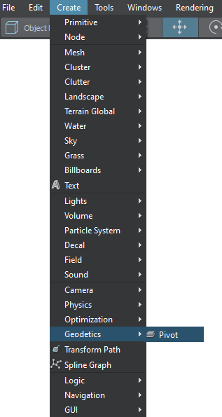
On the Menu bar, click Create -> Geodetics -> Pivot.
- Place the Geodetic Pivot somewhere in the world.
Setting Up a Geodetic Pivot#
After adding the Geodetic Pivot on the scene, set up the parameters located in the Geodetic Pivot section (Parameters window -> Node tab).
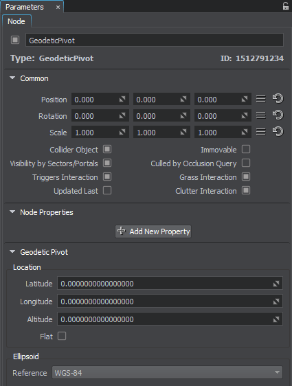
Location settings. The geodetic location on the Earth of the pivot point. It is specified by 3 components:
- Latitude is the north–south position in degrees of a point on the Earth's surface. For example, Tomsk city latitude is 56.4977100. 0 value means equator, 90 value means the North Pole, -90 means the South Pole.
- Longitude is the east-west position in degrees of a point on the Earth's surface. For example, Tomsk city longitude is 84.9743700. 0 value means a prime meridian (Greenwich). This field supports two ranges: from -180 to 180 and from 0 to 360.
- Altitude is the height above sea level of a location. For example, Tomsk city altitude is 117 meters.
- Flat geopositioning mode of the Geodetic Pivot. This mode should be used, when it is necessary only to set node positions via geo coordinates (latitude, longitude, altitude) without curving the terrain, clouds, etc.
Ellipsoid settings.
- Reference is a mathematically defined ellipsoid that approximates the surface of the planet. We offer popular geocentric reference ellipsoids: WGS84, GRS80, Airy 1830, etc.
Working with Geodetic Pivot#
After adding and setting up the Geodetic Pivot, you can simply add objects to "curve" them:
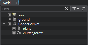
Choose the necessary nodes (Static Mesh, Grass, Clutter, etc.) in the Nodes window and set them as children of the Geodetic Pivot.
- Specify the necessary settings of the Geodetic Pivot.
- The update will be performed automatically.
As you add a node as a child to the Geodetic Pivot, its geo position coordinates (latitude, longitude, and altitude) are displayed in the Geo section of the Node tab:
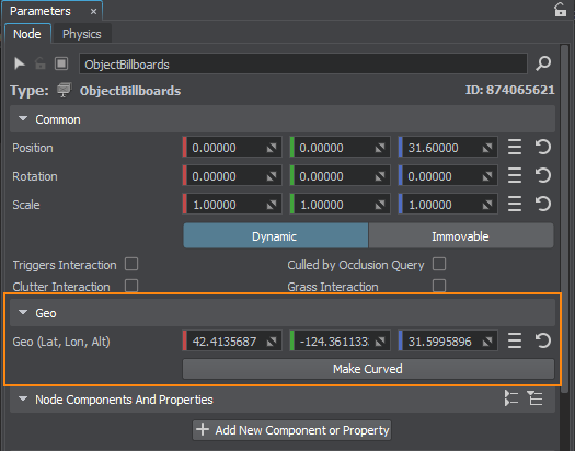
| Geo (Lat, Lon, Alt) | Specifies the geo position coordinates for the node (latitude, longitude, and altitude). |
|---|---|
|
By default only the following objects are curved by the Geodetic Pivot:
As for Static Meshes, Mesh Decals, and Billboards, sometimes you might just want to set their positions in real world coordinates an leave their geometry as is, but in some cases they should be curved (e.g., large static meshes, or roads represented as mesh decals). For this purpose you should use the following button: |
|
| Make Curved | Curves the geometry of the object according to the specified settings. A curved clone of the initial node is created, the initial node (using a non-curved mesh) is simply disabled, so you can use it when you need to return geometry back to normal (uncurved) state. |
The information on this page is valid for UNIGINE 2.20 SDK.