CAD Import Guide
CAD assets are imported into UNIGINE as any other asset. The following CAD formats are supported:
- IGES
- STEP
- STL
- BREP
Importing CAD Asset#
When you import a CAD asset, the import settings window appears:
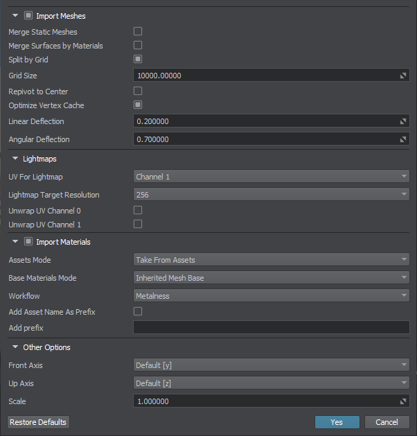
The list of available import options includes the following:
Mesh Import Options#
| Import Meshes | Import geometry meshes from the file. |
|---|---|
| Merge Static Meshes | Merges all children static meshes in one (names it after the parent mesh). All of the meshes surfaces will be copied and shown in the Surfaces hierarchy. |
| Merge Surfaces by Materials | Enables merging surfaces that have the same materials. |
| Split by Grid |
Enables splitting of imported meshes. Too large models having sizes, that exceed 10000 units may have various artefacts (jitter, etc.) associated with positioning errors. You can eliminate such artefacts by splitting your mesh into multiple separate meshes. To do so, just enable this option and set the size of the grid cell (see the Grid Size parameter below) to be used for mesh splitting. Notice
This option does not split surfaces. |
| Grid Size | Size of the grid cell to split imported meshes, in units. |
| Repivot to Center | Places a pivot of generated mesh to its center. Can be used for meshes having their geometry located too far from their pivot, as this may lead to various artefacts (jitter, etc.) associated with positioning errors. |
| Optimize Vertex Cache | Enables vertex cache optimization. This option reorders an indexed triangle list to improve vertex cache utilization at runtime. It can be turned off to accelerate saving process; however, it should always be turned on if saving the final version. |
| Linear Deflection | Limits the distance between triangles and the original surface. It is used to define triangulation of the imported model together with the Angular Deflection. |
| Angular Deflection | Limits the angle between adjacent triangles generated from a surface. It is used to define triangulation of the imported model together with the Linear Deflection. |
| Use LODs | Defines if Levels of Detail (LODs) are to be used for the imported model. |
Levels of Detail#
Automatic LOD Generation feature based on the meshoptimizer library will help create several variations of one object with different level of detail (LODs).
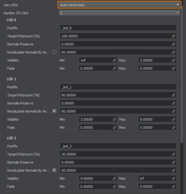
To use the feature choose Auto-Generated in the Use LODs dropdown and configure the settings listed below - the Engine will do the rest, generating all LODs automatically based on your configuration.
You can also enable the Merge Static Meshes option for more optimization.
Lightmaps Options#
Material Import Options#
| Import Materials | Enables importing materials from the file. Materials are stored in the .step, .stp and .iges, .igs files. When importing, only the albedo (diffuse) color is copied. Other material parameters should be set up after the model is added to the scene. |
|---|---|
| Assets Mode |
Enables to choose whether to use existing materials or to overwrite them with the ones imported. Available options:
|
| Base Materials Mode | Enables to choose the base material for the imported materials. Available options:
|
| Workflow |
Provides an interface to choose a workflow for the imported physically-based materials (if any). Available options:
|
| Add Asset Name as Prefix | Appends the name of the imported asset as a prefix to the imported materials names. |
| Add Prefix |
Appends the specified prefix for the imported materials names to avoid name collisions. Notice
If multiple CAD models are imported together this feature does not guarantee that all materials with the same names will be preserved, as only one prefix is used for all of them (if two models have different materials named black, only one of them shall remain with the specified prefix). To avoid such cases, models should be imported sequentially with different prefixes. |
| Merge Similar Materials | Merge materials with identical settings but having different names. |
Texture Import Options#
| Import Textures | Import textures stored in the CAD file. If textures are imported, the corresponding texture assets are created in the same folder, where the CAD asset is stored. |
|---|---|
| Invert G-Channel For Normal Maps | Invert the G-channel in normal maps. |
Other Import Options#
| Front Axis | Provides an interface to choose an axis to be considered as the forward vector of the World Coordinate System. |
|---|---|
| Up Axis | Provides an interface to choose an axis to be considered as the up vector of the World Coordinate System. |
| Scale |
Geometry scale multiplier. Notice
The default unit of length for CAD models can be millimeter, inch, etc. On model importing, it is transferred to meter used in UNIGINE. So, you may need to scale the model on importing to get the appropriate size. The specified value doesn't affect scale of the model added to the world. |
Hierarchy Options#
This auxiliary section is available in the Parameters window when selecting an imported CAD asset in the Asset Browser. It enables you to preview the content of the CAD asset imported with the current Mesh Import Options.
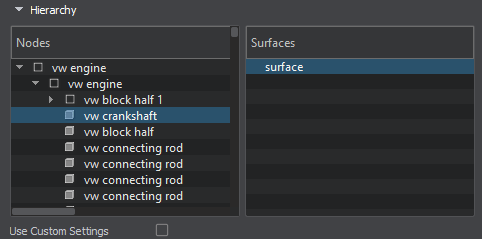
| Nodes | List of nodes obtained from the CAD asset. |
|---|---|
| Surfaces | List of surfaces of the selected node. |
| Use Custom Settings | Enables custom Lightmaps options for the selected surface(s). |
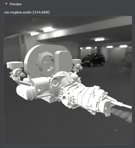
Asset Preview#
This section is available in the Parameters window when selecting an imported CAD asset in the Asset Browser. It allows you to preview the imported model.
Geometry#
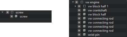
CAD model can be represented as a single detail or as an assembly. If parts of the assembly are stored in separate files, you should specify all of them on the assembly import.
To import 3D geometry data contained in a CAD model, you should enable the Import Meshes option. When you add the imported geometry to the scene, it will be available in the World Hierarchy as a Dummy Node:
- If the imported CAD asset stores a detail, a single static mesh will be a child of the Dummy Node.
- If the imported CAD asset stores an assembly, the Dummy Node will have a hierarchy of child nodes representing parts of the assembly.
By default, the surfaces of each detail of the CAD model that have the same material are merged resulting in a single surface for each detail in most cases.
If you enable the Merge Static Meshes option, all child meshes will be combined into a single one. At that, all surfaces of child meshes will be copied to the single parent mesh and will appear in its Surfaces hierarchy.
You can also merge the surfaces of the CAD model having the same material assigned by enabling the Merge Surfaces by Materials option.
Usually, the unit of length of the CAD models differs from meters. When importing a model into UNIGINE, it is transferred to meters. It may lead to improper size of the imported model: to adjust the scale of the imported geometry, you can use the Scale parameter.
It is also possible to optimize the vertex cache when importing geometry. To do so, use the Optimize Vertex Cache option.
Materials#
A CAD model can also store materials assigned to surfaces of the details. To import materials from a CAD model, enable the Import Materials option. In this case, the surfaces of the imported model will have the corresponding materials assigned.
When the Import Materials option is disabled, all surfaces of the model will have the default mesh_base material assigned.
When importing materials, you might have a situation when a material with a given name already exists in the project. You can choose whether to overwrite existing materials (the corresponding assets will be overwritten) or not. For this purpose, the Overwrite Assets option is used. When unchecked, the existing materials will be used.
Also you can choose the base material for the imported materials: it can be an autoselected/autogenerated graph-based material or the built-in mesh_base material.
If the Base Materials Mode is set to Inherited Mesh Base, you should use the Workflow option to set the desired one. UNIGINE supports two workflows for PBR materials: Metalness and Specular.
Adding Imported CAD Asset to the World#
To add an imported CAD asset to the scene, drag it from the Asset Browser to the Viewport window. The corresponding node will be created and displayed in the World Hierarchy window. This node will have the same name as the imported CAD asset and a hierarchy of child nodes representing separate objects contained in the model.
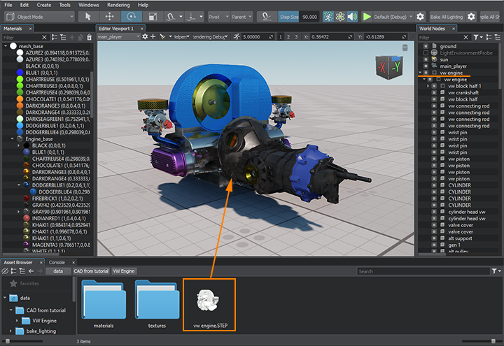
If you double-click the imported CAD asset in the Asset Browser, the .mesh and .node files generated in run-time and stored in the CAD file will be displayed.
The information on this page is valid for UNIGINE 2.20 SDK.