Camera Matrices
In UNIGINE, a camera has 2 matrices: the view and projection ones. They are used in rendering of the image from the camera to the viewport.
Before getting to the main aspects of the camera matrices, it is necessary to know peculiarities of the coordinate system used by UNIGINE and refresh general knowledge of vector spaces and transformation matrices used for vertex rendering.
Coordinate System#
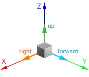
The 3D space in UNIGINE is represented by the right-handed Cartesian coordinate system: X and Y axes form a horizontal plane, Z axis points up.
Axes and Directions#
For nodes in the virtual scene:
- The +Z axis is considered the upward direction. To move the node up/down, translate it along the Z axis.
- The +Y axis is considered the forward direction. To move the node forward/backward, translate it along the Y axis.
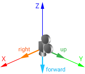
- The +Y axis is considered the upward direction.
- The -Z axis is considered the forward direction.
A camera with a default identity transformation matrix looks down:
Working with Directions#
As you can see, direction vectors of nodes and cameras differ. For example, if you need to get the forward direction of the node, you should call the getAxisY() method for its transformation matrix:
// get the node transformation matrix
Mat4 t = node->getWorldTransform();
// get the node "forward" vector from the matrix
vec3 node_forward = t.getAxisY();
And if you need to get forward direction of the camera, you should call the -getAxisZ() method for its transformation matrix:
// get the inverse modelview matrix as it is equal to the world transformation one
mat4 camera_transform = camera->getIModelview();
// get the camera "forward" vector from the matrix
vec3 camera_forward = -camera_transform.getAxisZ(); // the negative Z vector will be returned
However, the camera can be set to a player node. In this case, if you simply call getAxisY() as for any other node, you will get the upward direction of the camera. To avoid this, implement the following:
// get the node transformation matrix
Mat4 t = node->getWorldTransform();
// get the "forward" vector from the matrix
vec3 forward = vec3(node->isPlayer() ? -t.getAxisZ() : t.getAxisY());
Forward direction of the node/camera (if set to the player node) can also be obtained by using the Node::getDirection()/getWorldDirection() method:
vec3 forward = node->getDirection(node->isPlayer() ? Math::AXIS_NZ : Math::AXIS_Y);Vector Spaces and Transformation Matrices#
There are the following vector spaces:
- Local space is a space in which all vertices of an object are defined relative to the center of this object.
- World space is a space in which all vertices of an object are defined relative to the center of the world.
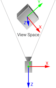
- View space is a space in which all vertices of an object are defined relative to the camera.
- Clip space is a space in which all vertices of an object are defined in a cuboid of [-1;1] dimensions for every axis. The Z coordinate of the vertex specifies how far away the vertex is from the screen.
- Screen space is a space in which all vertices of an object are flattened and have screen coordinates.
When rendering a vertex, it is transformed from one space into another in the following order:
![]()
The matrices used to transform between spaces are the following:
-
World Transformation Matrix stores transformation of the object relative to the world origin. This matrix is used to transform the the object's vertices from the local space to the world space: the matrix is multiplied by each vertex of the object.
In UNIGINE, such transformation is performed automatically when the node is added into the world. When a node is added into the world as a child of another node, it has also a Local Transformation Matrix that stores transformation of the object relative to its parent. To transform the local transformation matrix of such an object to the world one, the object's local transformation matrix is multiplied by the local transformation matrix of the parent. To get more information about local and world transformation matrices, check the Matrix Hierarchy chapter.
-
View Matrix is used to transform the object's vertices from the world space to the view space.
NoticeIn UNIGINE, the view matrix is called modelview. - Projection Matrix is used to transform the object's vertices from the view space to the clip space.
Each node added into the world has the world transformation matrix. However, passing this matrix to a shader for vertex rendering is unreasonable: it will lead to precision loss because of double to float coordinates conversion. For this reason, in UNIGINE, the node is transformed to the view space first: the product of the world transformation matrix and the view matrix is calculated on CPU and passed to the shader. Such matrix is called Modelview (in its generic meaning).
Thus, transformation of coordinates of an object's vertex can be represented by the following formula:
VertexClip = ProjectionMatrix * ModelviewMatrix * VertexLocalHere the ModelviewMatrix is the product of the world transformation matrix and the view matrix. The order of matrix multiplication is read from right to left.
View Matrix#
In UNIGINE, the View matrix is the 4x4 matrix that controls the way the camera looks at the scene. The view matrix is equal to the inverse camera world transformation matrix: it stores position and rotation of the camera in world space.
The matrix is used to transform vertices of the object from the world space to the view space (coordinates of vertices are set relative to the camera origin): the camera's view matrix is multiplied by the object's world transformation matrix and then the resulting matrix is multiplied by the object's vertices.
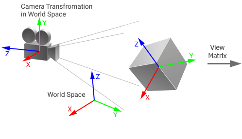 |
 |
Object and camera in world space |
Object in view space |
Projection Matrix#
The Projection matrix is a matrix that defines how vertices are rendered on the screen. The values of the projection matrix depend on the type of projection:
-
For the orthographic projection, the following matrix is used:
-
For the perspective projection, the following matrix is used:
By default, the projection matrix of the camera doesn't store an aspect ratio of the screen (width to height): aspect correction is performed automatically for the current viewport. If manual aspect correction is done, the automatic aspect correction for the viewport must be disabled to avoid incorrect results.
If you change FOV (or width and height for orthographic projection), near and far clipping planes, the matrix is updated.
The projection matrix is used to transform vertices of the object from the view space to the clip space. This space is represented by a cuboid with [-1;1] dimensions for every axis and used for clipping vertices: all vertices inside this volume will be rendered on the screen. In this space, the Z coordinate of each vertex specifies how far away a vertex is from the screen.
Then the vertex coordinates in the clip space are automatically transformed to normalized device coordinates by using perspective division. Mapping these coordinates to the screen space is performed on GPU by using the viewport transform vector that stores the following:
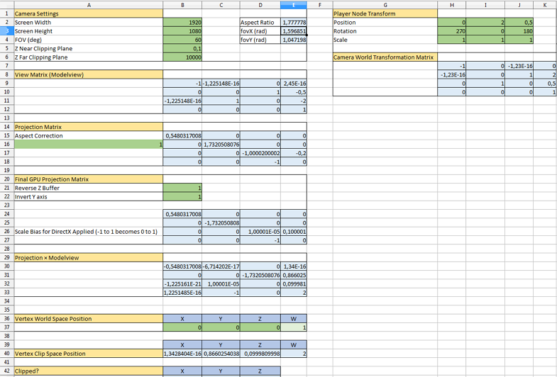
(width, height, 1/width, 1/height)Camera Matrices Simulator#
Take a look at the following spreadsheet to get a full picture of how camera matrices are handled in UNIGINE. It shows the way the World Transformation, View, and Projection matrices affect the coordinates of a vertex which can be used for debug purposes.