校准网格
SpiderVision has the calibration grid that can be enabled to align projections in such a way that the connection between them is seamless and the displayed image is not distorted. When the calibration grid is enabled, you don't see the rendered image, but see the grid. Using this grid, you can use the projection setup features to easily align projections.SpiderVision具有校准网格,可以对齐投影,使它们之间的连接无缝,显示的图像不会失真。启用校准网格时,您不会看到渲染的图像,但会看到网格。使用此网格,您可以使用投影设置功能轻松对齐投影。
The Calibration Grid setup window is available via the menu: Tools -> Calibration Grid.Calibration Grid设置窗口可通过菜单:Tools -> Calibration Grid。

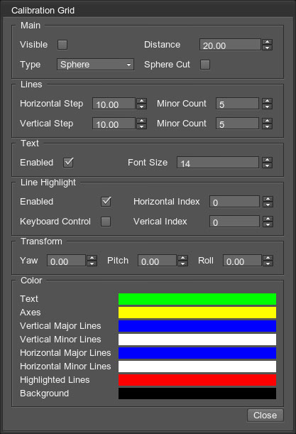
The following groups of calibration-related options are available:可提供以下几组与校准相关的选项:
| Main settings controlling the general view of the calibration pattern.Main设置控制校准模式的一般视图。 | |
| Visible |
Toggles displaying the calibration pattern on the projection.切换在投影上显示校准模式。 |
|---|---|
| Distance |
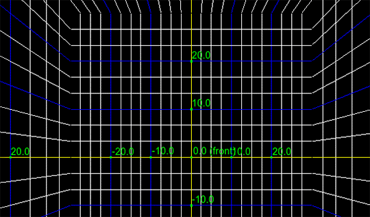
Distance from the camera to the grid. The difference is noticeable with the Box type of projection.摄像头到网格的距离。这种差异在Box类型的投影中是明显的。 从相机到网格的距离。 不同之处在于盒式投影。 |
| Type |
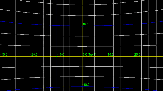
Type of the calibration pattern:校准模式的类型:
|
| Sphere Cut |
Allows hiding the top and bottom poles of the sphere for the Sphere-type calibration pattern.允许隐藏球体的顶极和底极,用于Sphere校准模式。 |
| Lines group of settings defines the distance between the lines and the number of minor (auxiliary) lines.Lines组设置定义线之间的距离和次要(辅助)线的数量。 | |
| Horizontal Step |
The distance between major horizontal lines.主要水平线之间的距离。 |
| Vertical Step |
The distance between major vertical lines.主要垂直线之间的距离。 |
| Minor Count |
The number of secondary lines between the two neighboring major lines. Is set individually for vertical and horizontal lines.两条相邻主线之间的次要线路的数目。分别为垂直线和水平线设置。 |
| Text group of settings allow enabling the text indications on the calibration grid and defining their size.Text组设置允许在校准网格上启用文本指示并定义其大小。 | |
| Line Highlight group of settings configures highlighting of one horizontal and one vertical line.Line Highlight组的设置配置突出显示一条水平线和一条垂直线。 | |
| Enabled |
Toggles the highlighting on and off.打开和关闭突出显示。 |
| Horizontal/Vertical Index |
Index of the line that is to be highlighted. The lines are invisible, when their indices are set to zero.要突出显示的线的索引。当它们的下标被设置为0时,这些线是不可见的。 |
| Keyboard Control |
When enabled, you can change the highlight index using the keyboard:启用后,您可以使用键盘更改突出显示索引:
|
| Transform group of settings allow transforming the grid along the vertical, transverse, and longitudinal axes. Only the grid is transformed, the projected image is not transformed.Transform组设置允许沿垂直、横向和纵向轴变换网格。只变换网格,不变换投影图像。 | |
| Color | Select colors for corresponding elements of the grid.为网格的相应元素选择颜色。 |
本页面上的信息适用于 UNIGINE 2.19.1 SDK.


