Generating Buildings
The Landscape Tool allows procedural generation of buildings based on shapes stored in the vector data sources.
Main Concepts#
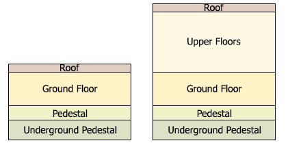
There are two types of buildings:
- Single-storey buildings, which have only one floor
- Multi-storey buildings, which have two or more floors
- Underground Pedestal is always 2 meters down from the Terrain level. This value is hardcoded and cannot be changed.
- The Pedestal height is defined by the Ground floor offset value and is 1 meter high above Terrain by default.
- The Ground Floor height is defined by the Floor height value and is 3 meters high by default.
- The height of Upper Floors equals Number of Upper Floors * Floor height.
Buildings Texturing#
UNIGINE provides a set of built-in materials for generated buildings: they are inherited from mesh_base and named according to the rules. You can also create your custom textures and set up materials. However, your textures should meet a set of requirements described below.
There are four types of textures that should be prepared for a building: a texture for the basement, a texture for the wall with openings (doors and windows), a texture for the solid wall, and a texture for the roof. The UV map of each part of the building depends on the size of the wall segment that is shown on the texture.
For Underground Pedestal and Pedestal, a single texture for a wall is applied. The texture height should correspond to the height of all these parts (in sum).
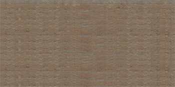 Texture for Underground Pedestal and Pedestal (Basement)
For the ground floor, an individual texture is applied. The texture height should correspond to the ground floor height.

 Texture with openings for Ground FloorSolid texture for Ground Floor
- For Upper Floors, a single texture for a wall with openings is applied. The texture height is usually multiple of the floor height. It can be multiple of the two, three, etc. floors height, however, it shouldn't exceed the height of the Upper Floors part.
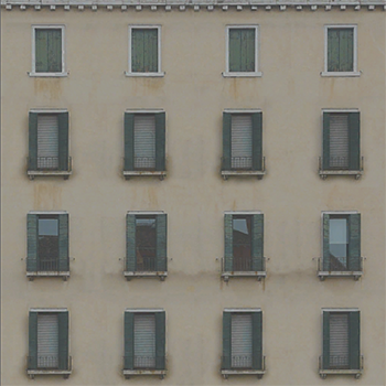
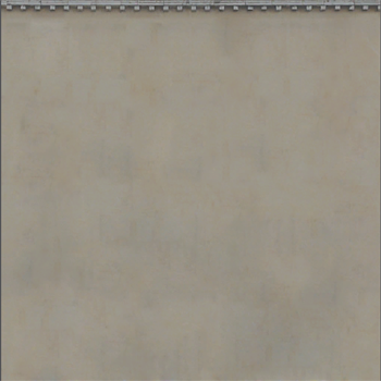 Texture with openings for Upper FloorsSolid texture for Upper Floors
 - If the wall width is less than the floor height, a segment of the texture with openings does not fit into this space properly, and the texture for a solid wall is applied.
- If the wall width is more than the floor height, the wall surface is split into two parts:
- The first part is tiled with a texture with openings. Its width is multiple of the floor height.
- The second part, where the texture with openings does not fit, is tiled with the solid texture.
For example, we have a two-storey building with the floor height of 3 meters. The sufrace of the second floor wall is 10.5 meters wide and is divided as follows:
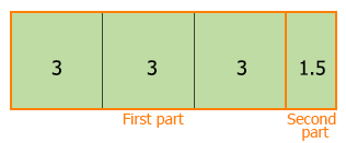
The texture for a wall with openings is applied to each 3*3 m segment (based on the floor height value). For the rest of the wall, the solid texture is applied.
- For Roof, two textures should be applied: the base and detail albedo textures. Using the detail texture allows you to diversify colors of roofs with the same material: set up details rendering (blending, masking, UV mapping, shading parameters of the texture) for the Roof material to achieve the required result.
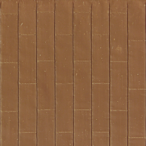
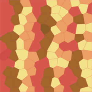 Base albedo textureDetail albedo texture
Materials Naming#
For materials to be correctly applied by the Landscape tool to the generated buildings, follow these rules:
- Each building category should have a separate base material inherited from mesh_base. This material is used as the material for the Ground Floor wall with doors and windows.
NoticeThe other materials applied to different parts of the same building are inherited from this one. The base material can have any desired name.For this material, a texture depicting the Ground Floor should be used.NoticeWhen specifying parameters of the buildings, only the base material is specified: its child materials are loaded automatically.
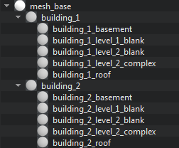
- Materials for the other parts of the building should be inherited from the parent material described in the previous paragraph and use the following name postfixes:
- _basement — a material for Pedestal and Underground Pedestal.
- _level_1_blank — a material for Ground Floor wall without doors and windows.
- _level_2_complex — materials for Upper Floors walls with doors and windows.
- _level_2_blank — materials for Upper Floors walls without doors and windows.
- _roof — a material for Roof.
For example, if you have 2 types of buildings that should have different materials, set up the following hierarchy:
1. Adding a Vector Data Source and Specifying Tags#
This step is the same as Adding a Vector Data Source and Specifying Tags for Spline objects.
2. Specifying Parameters of Buildings#
On the Sources panel, select the Vector data source type, and the following settings will be displayed in the 2.5D Buildings tab of the Parameters panel.
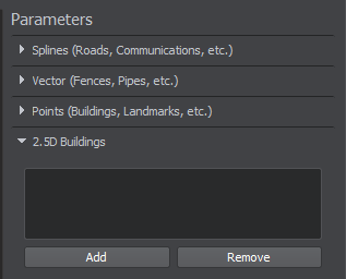
- Add a basic object for generation by clicking the Add button at the top of the Parameters panel and specify the object's name. You can add as many objects as necessary.
- For each basic object, specify the following parameters:
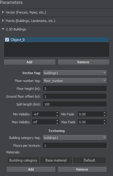
Vector tag The tag to be used for the selected object from the list of the tags specified at the first step. This tag is used to select data from the vector source. Floor number tag The tag that is used to read the number of building floors from the vector source. Floor height The height of a floor in the generated buildings. The default value is 3 meters. Ground floor offset The height of Pedestal. The default value is 1 meter. Split length The size of the grid cell by which the generated geometry will be divided. Geometry of each cell is represented as a separate ObjectMeshStatic object. If the specified value exceeds or equals to the size of the Play Area, a single static mesh will be generated. For example, if you specify 10000, for each 10000x10000 km cell, a separate static mesh will be generated. Min Visibility Minimum visibility distance from the camera at which generated objects (ObjectMeshStatic) start to appear on the screen. By default, this value is -inf. Max Visibility Maximum visibility distance at which generated objects (ObjectMeshStatic) are no longer fully visible: they can either disappear completely or start to fade out. By default, this value is inf. Min Fade Minimum fade distance, over which generated objects (ObjectMeshStatic) fade in until they are completely visible. Along this distance, the engine automatically interpolates the level of detail from alpha of 0.0 (completely invisible) to 1.0 (completely visible). Fading in starts when the camera has reached the minimum visibility distance and is in the full visibility range. Max Fade Maximum fade distance, over which generated objects (ObjectMeshStatic) fade out until they are completely invisible. Fading out starts when the camera has reached the maximum visibility distance and is out of the full visibility range. Building category tag The tag is used to read the building category from the vector source. Materials are assigned to buildings based on the value of this tag. The value must be an integer.
For example, you can specify the type tag here: buildings of different types (garages, apartments, houses) will have different materials applied.Floors per texture The number of Upper Floors for which a single texture is applied: - If the texture height corresponds to the height of a single floor, this value should remain 1. The texture will be applied for each floor.
- If the texture height corresponds to the height of two/three/etc. floors, this value should be set to 2/3/etc. The texture will be applied for every two/three/etc. floors.
- If the texture height is equal to the height of the Upper Floors part, this value should be equal to the number of Upper Floors.
Materials Materials that are applied to buildings generated for the basic object: - Building category — the category of buildings for which the material is applied. Here the value of the Building category tag should be specified.
- Base material — the base material for the specified building category.
- Default — the flag indicating if the material of this building category should be used as the default one. It is applied when the vector source contains no data on the building category or no material is specified for the building category.
The garage material and its children are applied to buildings with value 1, the villa material — to buildings with value 2, etc. In addition, the apartment material, being the default material, is applied not only to buildings with value 4, but also to buildings that have no value assigned, or have a value that is not specified in the list.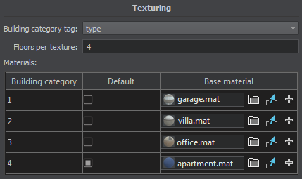
- Select basic objects that you want to be generated.
NoticeIf you are going to update some of the existing buildings, select only the changed ones. Buildings that are not selected remain unchanged after terrain regeneration.
3. Generating 2.5D Buildings#
Now you can generate buildings by clicking the Generate button and selecting the Vector objects option in the Steps window. In this case only vector objects will be generated.
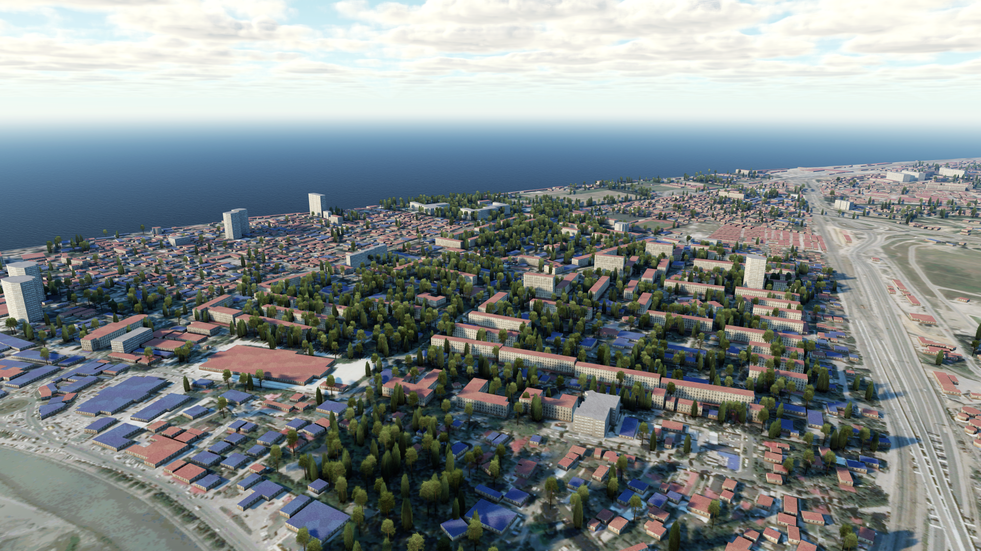
To regenerate a certain part of existing buildings, select only the basic objects that should be updated, click Generate and select the Vector objects option. Only the selected buildings will be regenerated. Basic objects that have not been selected remain unchanged.
