Terrain Options
Adding Terrain
There are three ways to add a Terrain object to the world:
- Load terrain from the existing terrain file.
- Import an externally created height map to create a new terrain with already defined relief. (As an option, the imported height map can be flipped around the Y-axis by checking Flip Y axis box.)
- Create a flat terrain grid and add relief using terrain brushes.
A terrain can be added with the following parameters:
| LOD | The distance to the first LOD that starts the distant-dependent tessellation. |
|---|---|
|
SizeX SizeY |
SizeX and SizeY set terrain dimensions along X and Y axes, i.e. how many grid cells there are along the X and Y axes. For example, if both SizeX and SizeY are equal to 256, the terrain will have 16×16 grid cells. |
| Step | The size of a grid cell in units. Step controls how big the created terrain will be. |
| Size (Import only) |
This additional option is enabled only if the Size checkbox is checked. It allows you to specify the size of the created square terrain in units (instead of specifying the Step size). |
| Height |
The maximum possible height for terrain relief. Set this value as low as possible. Each terrain vertex stores its height in range from 0 to 32768, that is, there are 32768 height levels available to describe elevation changes in range from 0 to the maximum Height in units. For example, if the Height is set to 1000 (if 1 unit = 1 meter), the minimum difference between the heights that can be created is 3 cm. But if the Height is set to 10,000, the minimum height change goes up to 30 cm. In this case the terrain would look edgy and coarse. |
|
Notice
SizeX, SizeY, Step and Height determine the maximum slope angle, namely the number of vertices at a given relative altitude. The bigger the grid sizes, the smaller the step and the height, the steeper the terrain slope can be. However, sometimes it is more rational to create very steep cliffs with a separate mesh, rather than to set very high density of terrain grid. |
|
Adding Base Textures
After Terrain object was added, textures can be imported or generated.
Heights Texture
| Import |
After the terrain object has been added, a height map can be imported in R8, RG8 or R16 formats (see details). The most common way is to generate terrain using a height map that contains altitude values for each terrain point. Remember that height maps should be created at the desired terrain size +1. For example, terrain of 256×256 size requires a 257×257 height map to cover all the vertices.
|
|---|---|
| Export |
A height map is exported into R16 format that is supported in DDS, PNG and PSD textures. Either the whole height map is available for export or a partial patch (i.e. several surfaces).
|
Holes Texture
| Import |
It is possible to import a one-channel texture (in R8 format) that defines where to place holes in the terrain: white color means there is a hole in the vertex, black means the vertex is of its proper height.
Notice
Holes are seen only on Patch levels (0-3 LODs). |
|---|---|
| Export |
A holes texture is exported into R8 format. Either the whole holes texture of the terrain is available for export, or a partial patch (i.e. several surfaces).
|
Diffuse Texture
| Import |
To add basic color to the terrain, diffuse texture is imported (RGB channels for color and alpha for specular highlights intensity).
|
|---|---|
| Export | A terrain-wide diffuse texture can be exported into any of formats supported in Unigine (as RGB8). |
| Create |
This option creates a blank diffuse texture that can be painted over, for example, in the terrain Editor. The blank coarse and surface diffuse textures will be created.
|
| Clear | This option clears coarse and surface diffuse textures, leaving the terrain white. By that, the texture files are not deleted from the disk. |
| Update coarse diffuse | This option allows for regeneration of a coarse diffuse texture at any time. It is necessary when diffuse texture was modified by hand in the terrain editing mode. Otherwise, if not updated, changes will be seen only on the Patch LODs and will disappear as soon as camera will move further away. |
Diffuse field is for the coarse diffuse texture.
Normal Map
| Create |
To light up the terrain, a normal map can be generated on the base of a height map. Vertex normals cannot be used for lighting since the terrain's triangulation changes over distance. So if per-vertex lighting were used, it would have resulted in changes of lighting every time the LOD is switched.
|
|---|---|
| Import |
Normal map import options allows for increasing visual details. You can generate normal maps based on big, highly detailed terrain in a 3rd party tool and after that apply it to a less detailed terrain in realtime.
|
| Export | A terrain-wide normal map can be exported into any of formats supported in Unigine (as RG8). |
| Clear | This option clears coarse and surface normal textures. By that, the texture files are not deleted from the disk. |
Normal field is for the coarse normal texture.
Mask for Detail Materials
| Import |
It is possible to add a Mask texture only after detail materials have been added in the editor, because the mask is mapped to material indices when imported. The mask specifies the visibility of detail materials (up to four per surface) throughout the terrain.
|
|---|---|
| Export |
A terrain-wide diffuse texture is exported as 3D texture (R8), where each layer is a separate mask for a detail material.
|
| Create | This option creates a blank diffuse texture that can be painted over, for example, in the terrain Editor. The blank coarse and surface diffuse textures will be created. |
| Create |
This option creates per-surface blank mask textures that can be painted over, for example, in the terrain Editor.
|
| Clear | This option clears per-surface mask textures, leaving the terrain without detail materials applied. By that, the texture files are not deleted from the disk. |
Compress All Textures
Optimizing Terrain Rendering
LODs
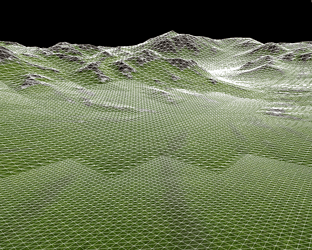
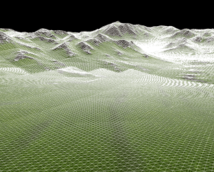
LOD allows to adjust the distance from the camera to the first LOD that starts distant-dependent tessellation.
 |
 |
Small LODs distance |
Bigger LODs distance |
Flatness
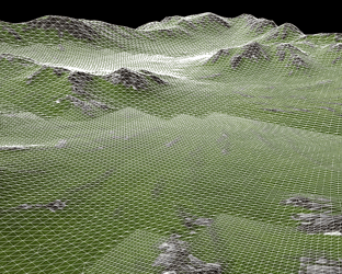
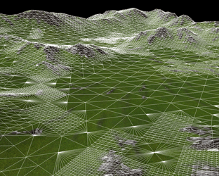
Adaptive tessellation allows to optimize rendering of plain and flat terrain areas. Instead of subdividing them with a fixed number of steps that the current LOD requires, tessellation adapts to the relief curvature and the viewpoint. The closer to the camera the curvature is and the more prominent it is, the more it gets subdivided. The flatness threshold tests the difference in heights between the polygons in the previous and next coming LOD. It is measured not in units, but in heights gradations.
- The minimum value of 0 means the tessellation is uniform and non-optimized.
- The higher the value, the greater the height difference between the polygons is possible to render polygons as one large patch.
 |
 |
Non-flattened terrain (Flatness = 0) |
Flattened terrain (optimized) |
How to Flatten the Terrain
Two problems appear after Flatten parameter is applied:
- There is no geomorphing for flattened polygons by switching the LODs.
- Intersection is checked according to the first, non-flattened LOD of terrain (the height map data). It means, that grass, WorldClutter and WorldCluster when growing or scattered across the terrain, do not follow the flattened relief. For example, some grass blades are hanging in the air, while the others are buried to deep instead of being rendered above terrain polygon.
This problems can be easily avoided if TerrainRelax tool is used. Follow the following steps to flatten the terrain:
- Tweak Flatness option to find out what flatness value is appropriate for your terrain.
- Export the current terrain height map (Terrain tab -> Heights: Export option).
- Run TerrainRelax tool. Set the same threshold (-t option) as the Flatness value chosen in the editor.
- Import the baked height map with flattened polygons (Terrain tab -> Heights: Import option).
- Set Flatness value to 0 in the editor.
Visible Distance
Visible distance sets the range passing which the terrain is no longer rendered. Not the entire terrain disappears at once, but rather starting from the furthest surfaces.
- If set to infinity (inf), there is no distant-dependent optimization for the terrain.
Shadow Distance
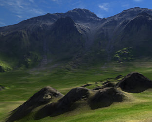
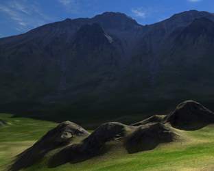
Shadow distance serves to limit the distance up to which mountains, hills and other relief features of the terrain cast shadows (Surfaces -> Cast shadows and Cast world shadows should be enabled for this option to be in effect).
- If set to infinity (inf), shadows will be casted across the whole visible terrain.
 |
 |
Shadow distance = infinity |
Shadow distance = 20 units |
Additional Shadow Radius
Radius is the distance to draw additional terrain polygons outside the view frustum. This option allows eliminating popping of shadows.
When the camera is looking down at the mountain foot, the peaks are outside the view frustum and do not cast shadow, though it should be visible. With Radius parameter, the geometry outside the camera view (in every direction across the chosen distance) is rendered and thus the shadows from mountain tops are in place.
- The shadow radius to set depends on the height of terrain relief features and the angle of the sun (which determines how long the shadows from it would be).
- Set the minimum possible value, as this parameter increases rendering load (check RTriangles counter in the performance profiler).
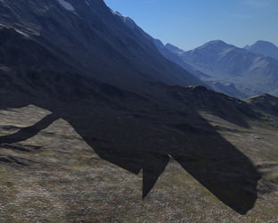 |
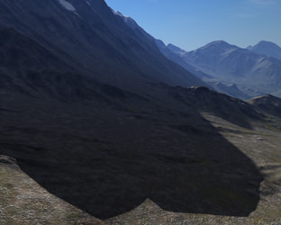 |
Radius = 0 |
Radius = 100 units |
Editing Surfaces Options
The Surfaces tab contains the list of surfaces into which a terrain is split and the order of materials that are present on this surface. Each surface can be excluded from rendering and detecting collisions with physical bodies if Enabled option is unchecked.
| Surface Textures | Each surface has a unique diffuse texture, normal map and mask texture. These are the patches into which imported textures covering the entire terrain are automatically split by import. All surface textures can be reloaded, if it is necessary to correct their coloring and lighting, without affecting the rest of terrain surfaces. | ||||
|---|---|---|---|---|---|
| Surface Flatness |
Flatness can be set separately for a surface. For example, if there are mountains as well as plains across the terrain, surfaces with hilly relief can have lower flatness and preserve their height variations, while surfaces with plains are flattened for optimized rendering.
|
||||
| Triplanar Texturing |
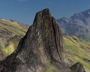
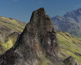
If steep heights and cliff-like slopes appear across a terrain, a simple planar projection of textures is not enough, as it produces severe stretching artifacts. To avoid them, trilinear texturing uses three different planar projections along each axis (X, Y, and Z). At any given point of the surface, its normal vector is analyzed and such projection is used which will be less stretched. In-between areas blend the appropriate projections together to texture the slope. For example, if a normal vector points mostly in the X-axis direction, the point will be textured mostly with YZ planar projection.
Notice
Height map based terrains are not designed for very steep slopes, cliffs or canyons, because the slopes will lack necessary geometry details. Meshes can be used to cover such areas.
|
||||
| Edit materials | Edit materials button allows to remove and change the order of detail materials appearing across a certain surface. A different channel will be used for masking detail materials in this case. |
