材质编辑器

Material Editor enables you to create your own materials visually without writing a single line of code — simply create and connect nodes building a graph! It is simple enough for users who are new to materials creation and powerful enough to let you do a lot of things. A brief list of features includes:材质编辑器使您无需编写任何代码即可直观地创建自己的材质:只需创建和连接节点以构建图形!对于刚接触材质创建且功能强大的用户来说,它足够简单,可以让您做很多事情。功能的简要列表包括:
- Ability to create your own base materials (.mgraph) and use them as directly assigned to objects or as parent materials for hundreds of other materials to avoid reassembling the material graph over and over again. The Materials hierarchy window will help you.能够创建自己的基础材质(.mgraph)并将它们直接分配给对象或用作数百种其他材质的父材质,以避免一遍又一遍地重新组装材质图。材质层次结构窗口将为您提供帮助。
- Ability to create your own custom graph nodes using other nodes (Subgraphs), or using your code. When you change the contents of a Subgraph, all materials using it will be updated as well.能够使用其他节点创建您自己的自定义图形节点(子图),或使用您的代码。当您更改子图的内容时,所有使用它的材质也会更新。
- Ability to switch between material types (there are five available at the moment: Mesh Opaque PBR, Mesh Alpha Test PBR, Mesh Transparent PBR, Mesh Transparent Unlit, Decal PBR).能够在材质类型之间切换(目前有五种可用:Mesh Opaque PBR, Mesh Alpha Test PBR, Mesh Transparent PBR, Mesh Transparent Unlit, Decal PBR)。
- Optional toggling of performance-affecting features on and off.可选择打开和关闭影响性能的功能。
- Ability to construct the final material's UI, you can add various parameters and even combine them into groups for convenience.能够构建最终材质的 UI,您可以添加各种参数,甚至可以将它们组合成组以方便使用。
- Connector — a special 'collapsed' mode of a graph node when it occupies less space and can be attached right to an input of another graph node.Connector 是图形节点的特殊“折叠”模式,当它占用较少空间并且可以直接附加到另一个图形节点的输入时。
- Expression — a special node enabling you to write simple arithmetic operations, but the main thing is that you can use it as a swizzle in combination with the ability to change the number of data components. Be sure you'll like it!Expression 是一个特殊的节点,使您可以编写简单的算术运算,但主要是您可以将它用作混合器,并结合更改数据组件数量的能力。确保你会喜欢它!
- Ability to write code in a special Function node, here you can implement even multiple functions calling each other.有能力写代码在一个特殊的 Function 节点中,在这里你甚至可以实现多个函数相互调用。
- You can drag-n-drop textures from the Asset Browser or directly from your file manager, and they will be automatically imported with the corresponding nodes added to the graph.您可以从资源浏览器或直接从文件管理器中拖放纹理,它们将自动导入并添加到图形中的相应节点。
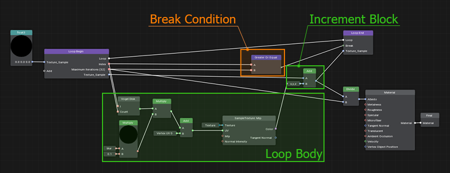
- Loops — a complex, but very cool feature enabling you to repeat an arbitrary sequence of actions multiple times. We have analyzed multiple existing implementations of graph loops and invented a new one that is almost on par with loops in code. Why not write loops in code then? Because using a graph makes implementation of complex things inside a loop much easier than doing the same in code.循环- 一个复杂但非常酷的功能,使您可以多次重复任意顺序的动作。我们分析了图循环的多种现有实现,并发明了一种几乎与代码中的循环相当的新实现。那么为什么不在代码中编写循环呢?因为使用图使得在循环中实现复杂事物比在代码中更容易。
- When working with complex or large graphs, you may end up with your wires are all over the place crisscrossing each other and you may want more visual clarity. That's when portals come into play. You can connect a wire to a Portal In node at one location and then place a Portal Out node at any other location you need and take what you've supplied to Portal In from a Portal Out (like you dug a tunnel for your wire under the node graph).在处理复杂或大型图表时,您可能会发现您的电线到处都是相互交叉的地方,您可能需要更清晰的视觉效果。那个时候门户参加进来。您可以将电线连接到一个位置的 Portal In 节点,然后将 Portal Out 节点放置在您需要的任何其他位置,并从 Portal Out 获取您提供给 Portal In 的内容(就像您在节点图下为电线挖了一条隧道) .
See Also也可以看看#
Material Graph Asset材质图资源#
A Material Graph asset (.mgraph) is both a source material network (node-based description to be compiled into a material) and a normal base material that can be assigned to a mesh surface.材质图资源(.mgraph)既是源材质网络(要编译成材质的基于节点的描述)又是普通基材可以分配给网格表面。
To create a new Material Graph, right-click in the Asset Browser to open the Create menu, then select Create Material -> Material Graph.要创建新的材质图,请在 Asset Browser 中单击鼠标右键以打开 Create 菜单,然后选择 Create Material → Material Graph。
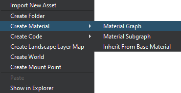
Specify a name for your graph asset. A new *.mgraph asset will be created in the current folder of your project.为您的图形资源指定一个名称。将在项目的当前文件夹中创建一个新的 *.mgraph 资源。
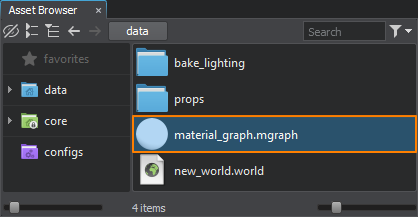
As the Material Graph asset represents a base material, it is also available in the root of the Materials Hierarchy and can be assigned to supported surfaces and objects. Depending on the material's type it can be assigned to the following objects:由于 Material Graph 资源表示基础材质,因此它也可以在材质层次结构并且可以是分配到受支持的表面和对象。根据材质的类型它可以分配给以下对象:
-
Mesh materials:网丝材质:
- Surfaces of Static, Dynamic, and Skinned meshes;Static, Dynamic和Skinned网格的表面;
- Surfaces of Mesh Clutter / Mesh Cluster.Mesh Clutter / Mesh Cluster的表面。
-
Decal materials:贴花材质:
- Projected, Orthographic, and Mesh decals.Projected,Orthographic, 和Mesh贴花。
Working with Material Graphs使用材质图#
Right-click on the *.mgraph asset and choose Edit Graph or simply double-click the asset to open it in the Material Editor window.右键单击 *.mgraph 资源并选择 Edit Graph 或直接双击资源以在 Material Editor 窗口中打开它。
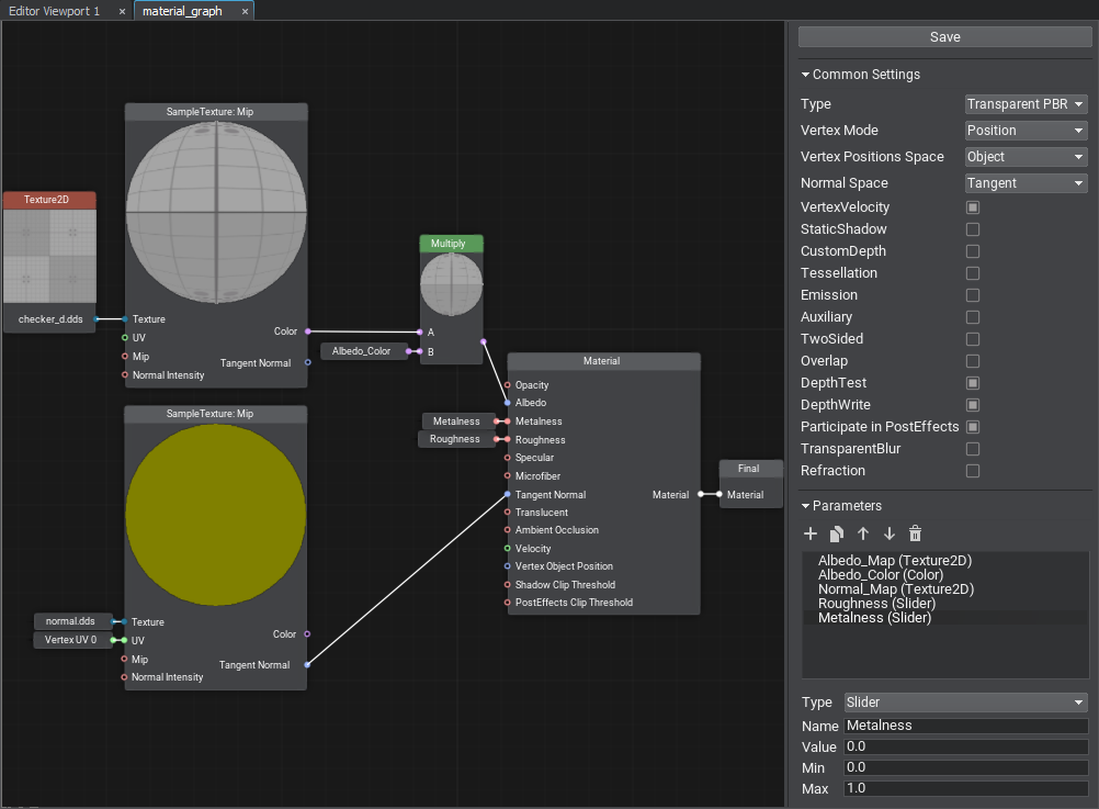
The Material Editor window includes the Graph View displaying the material graph network and the settings panel.Material Editor 窗口包括显示材质图网络的 Graph View 和设置面板。
The material graph network consists of nodes — functional blocks accountable for processing input data. By composing the graph network, you define the look of your material.材质图网络由节点--负责处理输入数据的功能块。通过组成图网络,您可以定义材质的外观。
The Material node is the master node of your material. It provides a set of inputs for graphic data and generates a material of a specific type depending on the current settings.Material 节点是材质的主节点。它为图形数据提供一组输入,并根据当前的情况生成特定类型的材质设置.
Finally, the output from the Master Node is connected to the Final node — the primary output material node.最后,主节点的输出连接到 Final 节点——主要输出材质节点。
Press the Save button to save changes and compile the material graph to a base material. Compilation errors, if any, will be listed in the Warnings and Errors panel and in the Console window.按 Save 按钮保存更改并将材质图编译为基础材质。编译错误(如果有)将列在警告和错误面板和 Console 窗口中。
Navigation Controls导航控件#
| Mouse Wheel drag | Pan material graph平移材质图 |
|---|---|
| Mouse Wheel scroll | Zoom in/out放大/缩小 |
| RMB / Space key | Display node creation palette显示节点创建面板 |
| LMB click | Select node / edge选择节点/边缘 |
| LMB drag on background | Select nodes with the rectangle tool使用矩形工具选择节点 |
| Shift + LMB on node | Add to node selection添加到节点选择 |
| Ctrl + LMB on node | Remove from node selection从节点选择中删除 |
| LMB drag on node | Move the selected nodes移动选定的节点 |
| Ctrl + C | Copy the selected nodes to the clipboard将选中的节点复制到剪贴板 |
| Ctrl + V | Paste nodes from the clipboard从剪贴板粘贴节点 |
| Ctrl + D | Clone the selected nodes克隆选定的节点 |
| Delete Key | Delete the selected nodes / edge删除选中的节点/边缘 |
Common Settings常用设置#
The Common Settings define the set of supported features for the material.通用设置定义了材质支持的特征集。
| Type | The type of the output material:输出素材的类型:
|
|---|---|
| Vertex Mode | Defines the mode for vertex adjustment and tessellation inputs:定义顶点调整模式和镶嵌输入:
|
| Vertex Space | Defines the vector space for vertex adjustment and tessellation. Options depend on the Vertex Mode selected:定义向量空间为了顶点调整和镶嵌.选项取决于所选的Vertex Mode:
|
| Normal Space |
Defines the space for normal vectors:定义空间法线向量:
|
| Depth Mode |
Defines how the Depth data is treated:定义如何深度数据被处理:
|
| Depth Shadow | Flag indicating whether custom depth affects shadows.指示自定义深度是否影响阴影的标志。 |
| Tessellation | Enables the Tessellation-related inputs and Tessellation settings.启用镶嵌相关输入和镶嵌设置。 |
| Two Sided | Enables the Two Sided option.启用 Two Sided 选项。 |
| Write Velocity Offset | Enables the Velocity input.启用 Velocity 输入。 |
| Advanced Mode | Enables the Compilation Settings.启用 编译设置。 |
Transparent Material Settings透明材质设置#
The following settings are available only for the Mesh Transparent PBR and Mesh Transparent Unlit material types.以下设置仅适用于 Mesh Transparent PBR 和 Mesh Transparent Unlit 材质类型。
| Blend Mode |
Blending preset. One of the following can be selected:混合预设。可以选择以下之一:
|
|---|---|
| Blend Src | Option used to scale the source color (the color of an overlaying material). Available only when Custom preset is selected.用于缩放源颜色(覆盖材质的颜色)的选项。仅在选择 Custom 预设时可用。 |
| Blend Dest | Option used to scale the destination color (the color of an obscured material). Available only when Custom preset is selected.用于缩放目标颜色(被遮蔽材质的颜色)的选项。仅在选择 Custom 预设时可用。 |
| Overlap | Enables the Overlap option.启用 Overlap 选项。 |
| Depth Test | Enables the Depth Test option.启用 Depth Test 选项。 |
| Depth Write | Enables the Depth Write option.启用 Depth Write 选项。 |
| Participate in PostEffects | Enables the Post Processing options.启用 Post Processing 选项。 |
Decal Material Settings贴花材质设置#
The following settings are available only for the Decal PBR material types.以下设置仅适用于 Decal PBR 材质类型。
| Normal Under Decal |
Defines the tangent space (Tangent-Binormal-Normal matrix) used for normal mapping:定义用于法线映射的切线空间(Tangent-Binormal-Normal 矩阵):
|
|---|---|
| Normal Blend Mode |
Blending mode for decal's normals:贴花法线的混合模式:
|
| Screen Projection | Enables Screen Projection of the decal instead of projecting it onto a surface (only Mesh decals are supported).启用贴花的屏幕投影,而不是将其投影到表面上(仅支持 Mesh 贴花)。 |
Compilation Settings编译设置#
These settings are only for the Direct3D compiler (DirectX API).这些设置仅适用于 Direct3D 编译器(DirectX API)。
| Optimization Level | Level of shader optimization and arithmetic refactoring (such as merging a multiply instruction followed by an add into a fused mad): 着色器优化和算术重构的级别(例如合并一个multiply指令后跟一个add融为一体 mad):
|
|---|---|
| Warning Mode |
The following modes are available: 以下模式可用:
|
| IEEE Strictness | Forces the IEEE strict compile.强制 IEEE 严格编译。 |
Parameters参数#

In the Parameters panel, you define the list of material parameters.在 Parameters 面板中,您可以定义材质参数列表。
The following controls are available:可以使用以下控件:
 Add — add a new parameter.
 Add 添加一个新参数
 Clone — clone the selected parameter.
 Clone 克隆所选参数
 Move Up — move the selected parameter up in the list.
 Move Up 将所选参数在列表中向上移动
 Move Down — move the selected parameter down in the list.
 Move Down 将所选参数在列表中向下移动
 Remove — remove the selected parameter.
 Remove 删除选定的参数
When adding a new parameter, you should specify the parameter's Name, Type, and default settings in the parameter creation dialog. The following set of parameter types is provided:添加新参数时,应在参数创建对话框中指定参数的Name 、 Type和默认设置。提供了以下一组参数类型:
- Slider — a float value within the specified range ([0.0f; 1.0f] by default).Slider--指定范围内的浮点值(默认为 [0.0f; 1.0f])。
- Color — a float vector of 4 components representing a color value.Color--表示颜色值的 4 分量的浮点向量。
- Texture2D, Texture3D, Texture2DArray, Texture2DInt, TextureCube — a texture of the corresponding type.Texture2D, Texture3D , Texture2DArray , TextureCube--对应类型的纹理。
- Group — an auxiliary type for grouping parameters. Use the
 and
and  buttons to rearrange and group parameters.Group--用于分组参数的辅助类型。使用
  和
和  按钮重新排列和分组参数。
 - Float, Float2, Float3, Float4 — a float value or a vector of N float values.Float, Float2, Float3, Float4--浮点值或 N 浮点值的向量。
- Int, Int2, Int3, Int4 — an integer value or a vector of N integer values.Int, Int2, Int3, Int4--整数值或 N 整数值的向量。
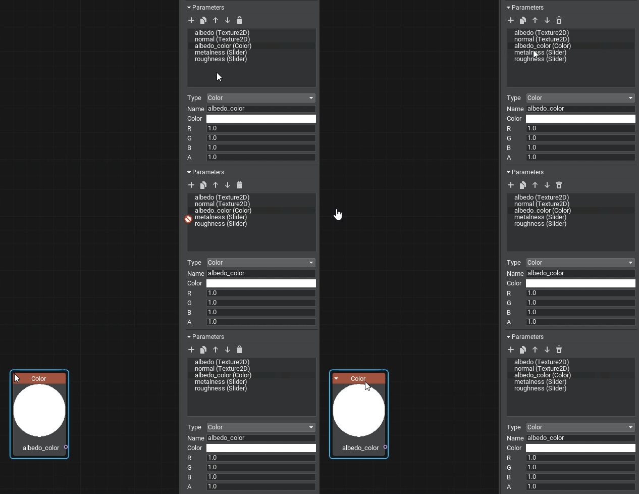
To use a parameter in your material graph, drag the item to the Graph View to create a node of the corresponding type:要在材质图中使用参数,请将项目拖到 Graph View 以创建相应类型的节点:
Warnings and Errors警告和错误#
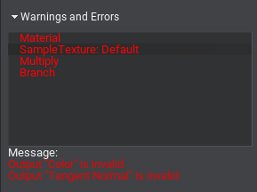
The Warnings and Errors panel enables you to track problems in the material graph and is visible only if there are any.Warnings and Errors 面板使您能够跟踪材质图中的问题,并且仅在有问题时才可见。
The panel lists all problem nodes in the graph, select an entry to see the problems with its ports or data in the Message section.该面板列出了图表中的所有问题节点,选择一个条目以在 Message 部分中查看其端口或数据的问题。
Some warnings may appear after migrating your content to a higher SDK version. These are reminder warnings meant to notify about changes in the logic of certain nodes. You can discard the warning by using the Remove Warning button.之后可能会出现一些警告迁移内容到更高的 SDK 版本。这些是提醒警告,旨在通知某些节点的逻辑变化。您可以使用 Remove Warning 按钮放弃警告。
Nodes节点#
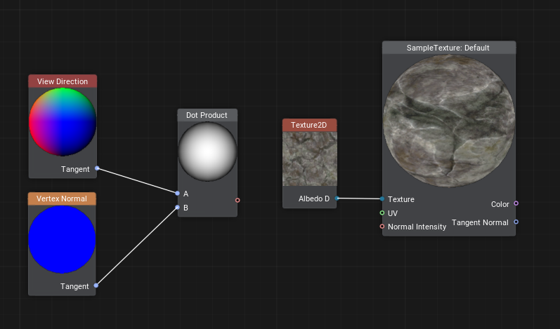
Nodes of Material Editor are functional blocks that represent data sources and processing instructions similar to variables and functions in shader programming.材质编辑器的节点是代表数据源和处理指令的功能块,类似于着色器编程中的变量和函数。
Most nodes have the output preview shown on a preview sphere (for most nodes) or a plane (for textures).大多数节点的输出预览显示在预览球体(对于大多数节点)或平面(对于纹理)上。
Some nodes have a set of settings defining their behavior. Double-clicking the node opens the dialog for adjustment of the node's settings.一些节点有一组定义它们的行为的设置。双击节点会打开用于调整节点设置的对话框。
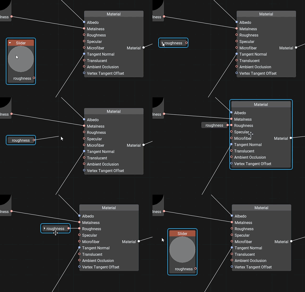
Nodes that have no more than one input and one output port have a special connector mode — they are collapsible for convenience. A collapsed node connected to another node becomes attached to it. Drag the collapsed node to break the connection and detach the node.不超过一个输入和一个输出的节点端口有一个特殊的连接器模式——为了方便,它们是可折叠的。连接到另一个节点的折叠节点将附加到它。拖动折叠的节点以断开连接并分离节点。
Nodes are split into several groups based on their applicability and color-coded for better identification.节点分为几组基于它们的适用性和颜色编码以便更好地识别。
Port端口#
A port defines an input (left side) or output (right side) of a node. Connecting edges to a port allows data to flow through the Material Graph node network.端口定义节点的输入(左侧)或输出(右侧)。连接边缘到端口允许数据流过 Material Graph 节点网络。
Each port has a data type defining edges that can be connected to it. All data types are color-coded, meaning that each of them has an associated color used for identification.每个端口都有一个数据类型,定义了可以连接到它的边缘。所有数据类型都用颜色编码,这意味着它们中的每一个都有用于识别的关联颜色。
 float
float float
float |
 float2
 float2
 |
 float3
 float3
 |
 float4
 float4
 |
 int
int int
int |
 int2
int2 int2
int2 |
 int3
int3 int3
int3 |
 int4
int4 int4
int4 |
 matrix — a matrix of float values: float2×2, float3×3, float4×4.
 matrix--浮点值矩阵: float2×2 、 float3×3 、 float4×4 。
 |
|||
 texture — any type of a texture: Texture 2D, Texture 3D, Texture 2D Array, Texture 2D Int and Texture Cube.
 纹理--任何类型的纹理:Texture 2D,Texture 3D, Texture2DArray 和Texture Cube.
 |
|||
 bool — a boolean value used in logical nodes and loops.
 bool--使用的布尔值逻辑节点和循环.
 |
|||
 any — arbitrary data type meaning the port supports several data types.
 any--任意数据类型,表示端口支持多种数据类型。
 |
|||
 error — indicates an error (e.g., no required input provided or type conversion has failed).
 error--表示错误(例如,未提供必需的输入或类型转换失败)。
 |
|||
Only one edge can be connected to any input port, but you can connect multiple edges to an output port.只有一个边缘可以连接到任何输入端口,但您可以将多个边缘连接到一个输出端口。
Most input ports have a default input value.大多数输入端口都有一个默认输入值。
Edge边缘#
An edge represents a connection between two ports (input and output). Edges define how data flows through the Material Graph node network. You can only connect an edge from an output port to an input port.一条边缘表示两个之间的连接端口(输入和输出)。边缘定义了数据如何通过 Material Graph 节点网络。您只能将输出端口的边缘连接到输入端口。
A new edge is created by dragging from the desired output port to the desired input port or vice versa. To remove an edge select it with the left click and hit Delete.通过从所需的输出端口拖动到所需的输入端口来创建新边缘,反之亦然。要删除边缘,请单击左键选择它并点击 Delete。
Port Adapters端口适配器#
Port adapter is a feature giving you the ability to select data components in an arbitrary order, combine and rearrange them, providing convenient access to elements and a lot of flexibility. It is available for the following data types:端口适配器是一项功能,使您能够以任意顺序选择数据组件,组合和重新排列它们,提供对元素的方便访问和很大的灵活性。它适用于以下数据类型:
- bool
- float, float2, float3, float4
- int, int2, int3, int4
When you drag a new edge to an input port, a number of available connection options shall appear:当您将新边缘拖动到输入端口时,将出现许多可用的连接选项:
- The = option provides the direct connection in the case the input type can provide all needed data components.在输入类型可以提供所有需要的数据组件的情况下,= 选项提供直接连接。
- Selecting another option creates an Expression node accountable for type conversion.选择另一个选项会创建一个负责类型转换的 Expression 节点。
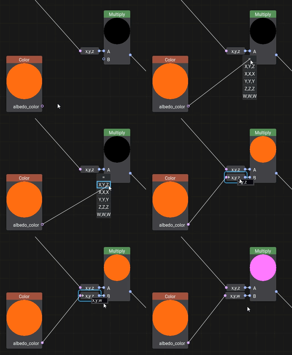
You can change the adapter later by double-clicking the expression and editing the field. The Expression node enables you to write simple arithmetic operations and even use the Unigine Graphic API.您可以稍后通过双击表达式并编辑字段来更改适配器。 Expression 节点使您能够编写简单的算术运算,甚至可以使用 Unigine 图形 API。
Adding New Nodes添加新节点#
In order to add a new node, right-click on the background or press Space and select a node type from the palette or type its name in the Search field to find it.要添加新节点,请右键单击背景或按空格键并从调色板中选择节点类型或在 Search 字段中键入其名称以找到它。
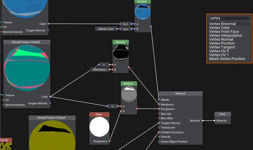
Dragging an edge from an input port opens a node creation palette with a pre-set filter to the required data type for the corresponding port.拖动一个边缘从输入端口打开一个节点创建调色板使用针对相应端口所需数据类型的预设过滤器。
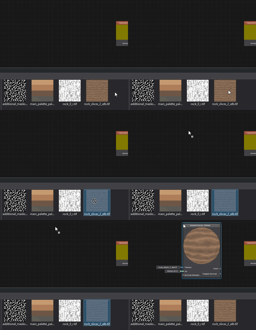
Textures can be dragged directly from the Asset Browser. In this case, a Sample Texture node with corresponding settings will be added automatically.可以直接从资源浏览器中拖动纹理。在这种情况下,将自动添加一个具有相应设置的 Sample Texture 节点。
Loops循环#
Sometimes you need to perform certain actions multiple times, cloning the relevant groups of nodes will make your graph overcomplicated very quickly, even if only 10 iterations are required. In UNIGINE, you can create loops for that, just like in programming. 有时您需要多次执行某些操作,即使只需要 10 次迭代,克隆相关的节点组也会使您的图变得非常复杂。在 UNIGINE 中,您可以为此创建循环,就像在编程中一样。
To create a loop, add the Loop Begin and Loop End nodes and connect their Loop ports.要创建循环,请添加 Loop Begin 和 Loop End 节点并连接它们的 Loop 端口。
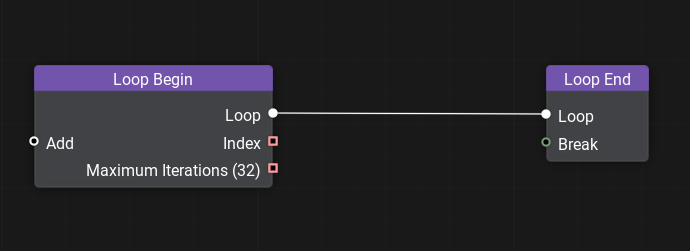
To add changing variables to the loop, connect nodes with starting values to the Add port of the Loop Begin node. By double-clicking the Loop Begin node, you can open the Input Constructor enabling you to rearrange, rename, delete existing inputs and implicitly set their type as well as set the maximum number of iterations.要将变化的变量添加到循环中,请将具有起始值的节点连接到 Loop Begin 节点的 Add 端口。通过双击 Loop Begin 节点,您可以打开 Input Constructor,使您能够重新排列、重命名、删除现有输入并隐式设置它们的类型以及设置最大迭代次数。
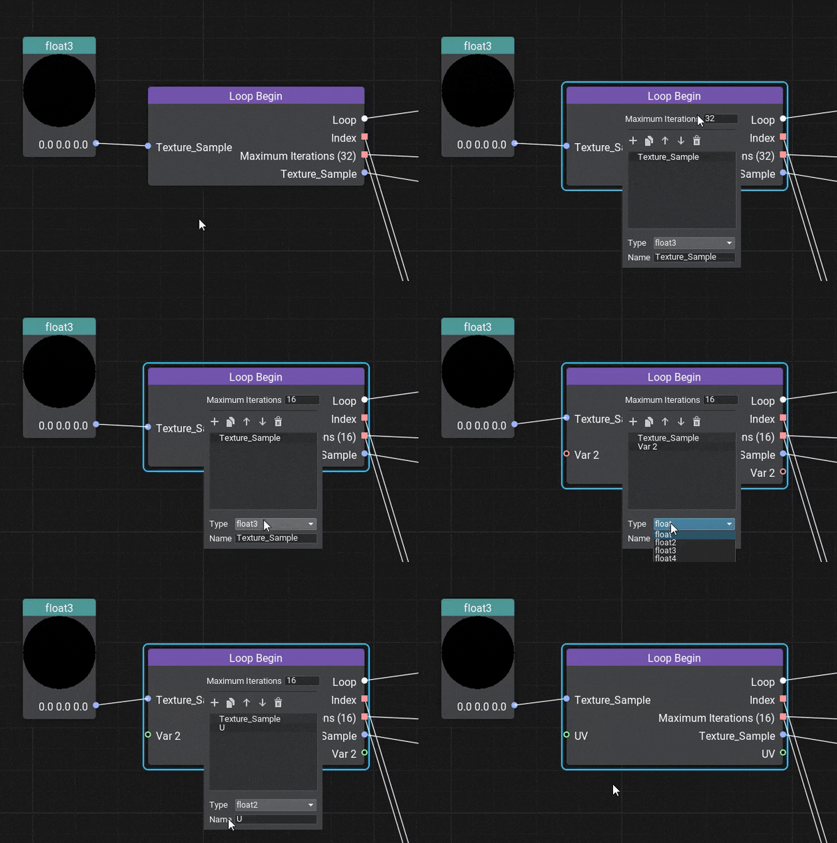
Then, build a graph implementing the functionality of a single iteration, the result of which should be passed to the Loop End node for further iterations. You can use the result of all iterations further in your graph.然后,构建一个实现单次迭代功能的图,其结果应传递给 Loop End 节点以进行进一步的迭代。您可以在图表中进一步使用所有迭代的结果。
You can use the Index of the current iteration and the Maximum Iterations values in your logic. The Index starts with 0 and is equal to Maximum Iterations-1 at the last iteration.您可以在逻辑中使用当前迭代的 Index 和 Maximum Iterations 值。 Index 以 0 开始,在最后一次迭代中等于 Maximum Iterations-1。
Here's an example of a simple loop, incrementing a value by 0.1 10 times:这是一个简单循环的示例,将值增加 0.1 10 次:
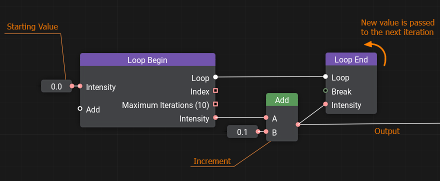
The Loop End node has the break input port that takes a boolean value, false by default. Passing a truth value (e.g., obtained via Logical Nodes) will interrupt the loop and exit the current iteration.Loop End 节点的 break 输入端口采用布尔值,默认为 false。传递一个真值(例如,通过逻辑节点)将中断循环并退出当前迭代。
Custom Code自定义代码#
No matter how advanced the materials system is, you might want something specific, maybe too complicated to implement via basic nodes. Or sometimes, it might be quicker to write several lines of code for mathematical operations instead of spawning a bunch of nodes and connecting them. The solution is simple — create a Function node and wrap any shader function into it. Input and output ports for the node shall be automatically generated according to the function's signature.无论材质系统多么先进,您都可能需要一些特定的东西,可能过于复杂而无法通过基本节点实现。或者有时,为数学运算编写几行代码可能会更快,而不是生成一堆节点并将它们连接起来。解决方案很简单:创建一个Function节点并将任何着色器函数包装到其中。输入输出 端口节点应根据函数的签名自动生成。
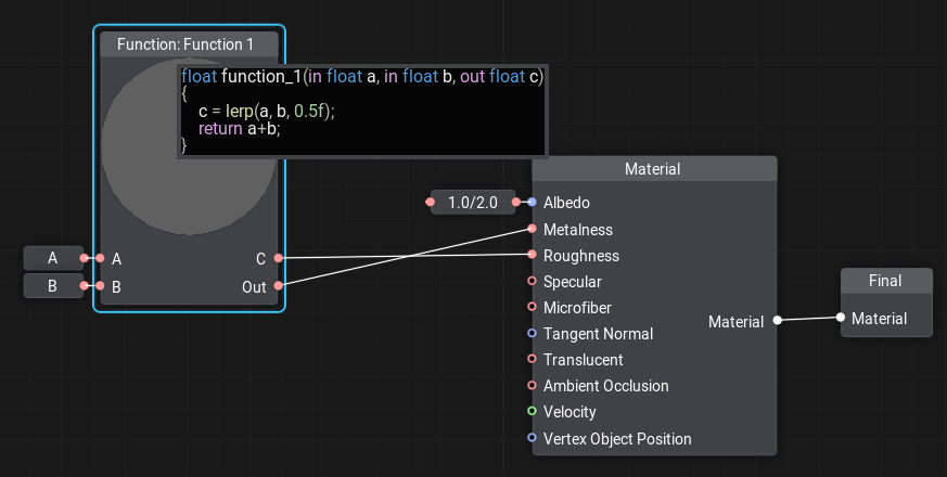
To add or edit code to the node double-click on the node, the Code Editor window will open. You can write as many functions as you need, the last function in the code will be considered the main one.要向节点添加或编辑代码,请双击节点,代码编辑器窗口将打开。您可以编写任意数量的函数,代码中的最后一个函数将被视为主要函数。
Portals门户网站#
Sometimes, especially in complex material graphs, there are too many crisscrossing edges making the whole graph look like a spiderweb, and the data flow very hard to understand. A portal is a set of special nodes including a single input and one or more outputs, all having the same name. Portals serve to reduce the number of edges and make the graph more 'readable'.有时,特别是在复杂的材质图中,有太多的交叉边缘使整个图看起来像蜘蛛网,数据流非常难以理解。门户是一组特殊节点,包括单个输入和一个或多个输出,它们都具有相同的名称。门户用于减少边缘的数量并使图形更具“可读性”。
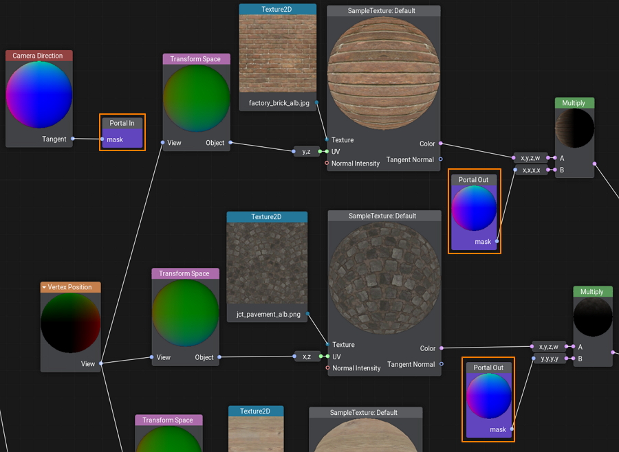
To create a portal, start with adding a Portal In node. Connect an input to the new node and double-click on it to adjust its color and name.要创建一个门户,首先要添加一个 Portal In 节点。将输入连接到新节点并双击它以调整其颜色和名称。
And then you can create as many Portal Out nodes as you need. By double-clicking on a Portal Out node you can select the name of the desired input portal in case several portals are used.然后您可以根据需要创建任意数量的 Portal Out 节点。通过双击 Portal Out 节点,您可以选择所需输入门户的名称,以防使用多个门户。
Subgraphs子图#
A Subgraph is a special type of material graph, which can be referenced from inside other material graphs. This can be very useful when the same operations are to be performed multiple times in a single graph or across multiple graphs. You simply pack these operations into a box with a set of inputs and outputs and then use this box anywhere you need. A Subgraph differs from a Material Graph in three main ways:子图是一种特殊类型的材质图,可以从其他材质图内部引用。当要在单个图形或跨多个图形中多次执行相同的操作时,这可能非常有用。您只需将这些操作打包到一个带有一组输入和输出的盒子中,然后在需要的任何地方使用这个盒子。子图在三个主要方面不同于材质图:
- A Subgraph does not generate any material, it is used as a building block in material graphs.子图不生成任何材质,它用作材质图中的构建块。
- A Subgraph does not have Material and Final nodes. Instead, it has two nodes called Inputs and Outputs, defining all input and output ports.子图没有Material和Final节点。相反,它有两个节点,称为 Inputs 和 Outputs,定义所有输入和输出端口。
- A Subgraph is stored in a *.msubgraph asset.子图存储在 *.msubgraph 资源中。
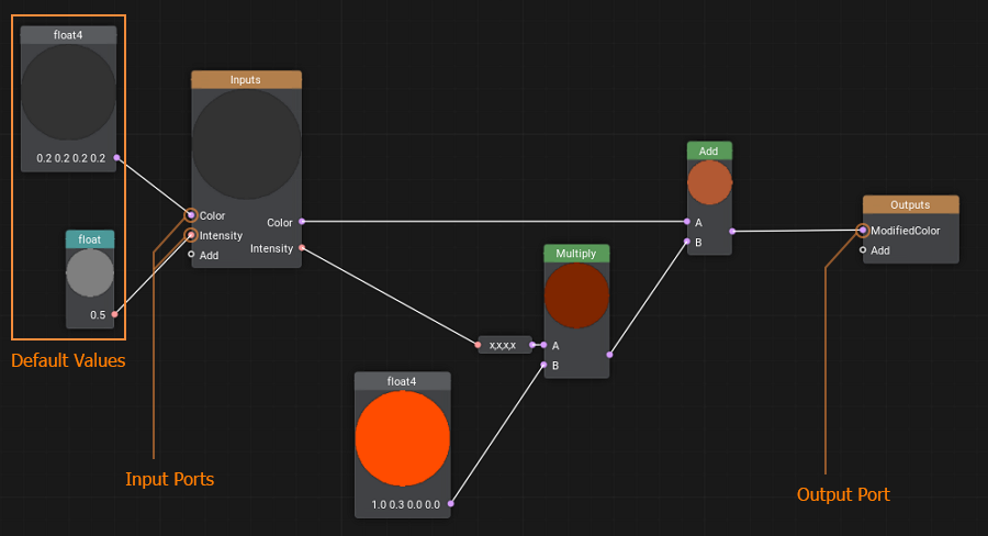
Basically, the process of construction of a Subgraph is the same as when you create a Material Graph.基本上,子图的构建过程与创建材质图时的过程相同。
To create a new Subgraph, right-click in the Asset Browser to open the Create menu, then select Create Material -> Material Graph.要创建新的子图,请在资源浏览器中右键单击以打开 Create 菜单,然后选择 Create Material -> Material Graph。
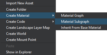
Click Save to apply and save changes.单击 Save 应用并保存更改。
All subgraphs are automatically added to the palette, so if your start typing a name of such a subgraph in the search field of the node creation palette, it will be displayed in the list.所有子图都会自动添加到调色板中,因此如果您开始在搜索字段中输入此类子图的名称节点创建调色板,它将显示在列表中。
Configuring Inputs and Outputs配置输入和输出#
Double click on the Inputs node or the Outputs node to open the constructor panel enabling you to add, rearrange, delete and set the name and type of input and output ports of the subgraph correspondingly.双击 Inputs 节点或 Outputs 节点打开构造器面板,可以对子图进行相应的添加、重新排列、删除以及输入输出端口的名称和类型的设置。
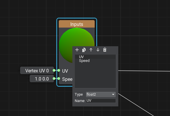
By connecting nodes to the ports of the Inputs node, you specify the optional ports of the subgraph having default values.通过将节点连接到 Inputs 节点的端口,您可以指定具有默认值的子图的可选端口。
Using Subgraphs使用子图#
To add a subgraph to your material graph currently opened in the Editor, simply find it by name in the node creation palette or drag it from the Asset Browser, or you can add the Sub Graph node to your graph network, specify the *.msubgraph asset by double-clicking the node, and connect necessary edges to input and output ports of the subgraph.要将子图添加到当前在编辑器中打开的材质图,只需在节点创建调色板或者从Asset Browser中拖动它,或者您可以将 Sub Graph 节点添加到您的图网络中,通过双击节点指定 *.msubgraph 资源,并将必要的边缘连接到子图的输入和输出端口。
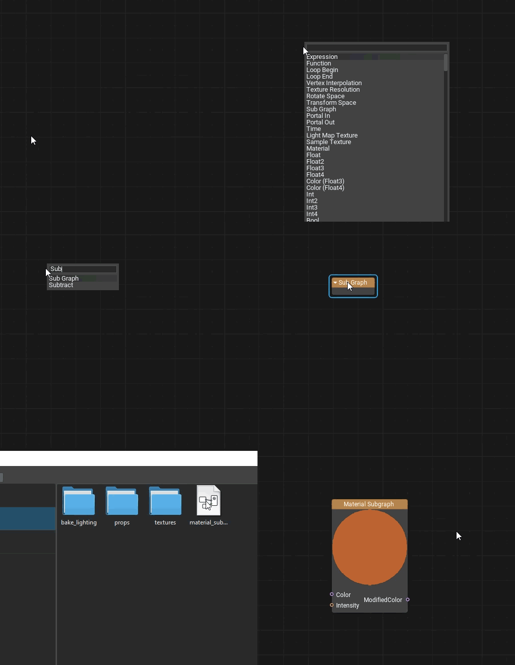
There is a set of core subgraphs implementing basic functionality (like contrast, refract, object_triplanar, etc.) stored in the core/subgraphs folder.core/subgraphs 文件夹中存储了一组实现基本功能(如 contrast, refract, object_triplanar 等)的核心子图。

