Terrain Optimization
A level of details (LOD) system automatically adapts the density of a terrain grid detailing according to the distance. There are two types of visibility levels that depend on the distance:
- A coarse level is the furthermost from the camera and the least detailed. On this level coarse diffuse, normal and mask textures are rendered. They are always stored in the memory and allow renderer to effectively render extremely large terrains.
- A refined level is closer to the camera and more detailed. When a terrain is created, its grid is automatically divided into smaller refined chucks of 257×257 vertices in size (shown in the Refined tab). Each surface has a unique set of textures, which, in fact, are parts cut out from the imported textures. Parameters of each surface can be modified either together or separately.
LODs Tessellation
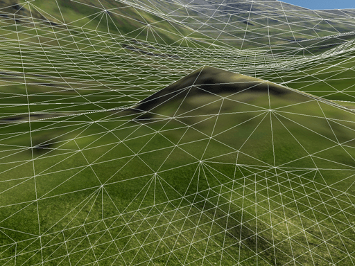
Terrain LOD system has smoothly adapting tessellation required to avoid seams and cracks in transition regions. Each vertex near the outer perimeter of a smaller LOD is seamlessly stitched to the neighboring polygons of a bigger LOD with additional triangles. The same technique is used to smoothly fuse heights and holes into the terrain.
Geomorphing
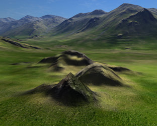
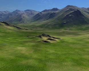
Another problem of switching between two tessellation levels is popping of vertices. For example, when polygons that form pyramid-like bump are abruptly switched to one flat polygon, it gives a very unpleasant popping effect. Geomorphing technique introduces an effective way out: before actually switching to the next LOD, it smoothly moves vertices down to their position, morphing the bump into flat surface. As a result, there are no artifacts visible; even in case of a very sparse grid and too small LOD distance only slightly moving vertices can be noticed.
 |
 |
Hummock from close-by |
The same hummock from further away |
LODs Settings
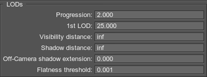
You can modify the following LODs parameters in the LODs field of the parameters tab:
- Progression - a coefficient to calculate the distances from the first LOD to other LODs.
- 1st LOD - the first level of details.
- Visibility distance - the terrain visibility distance.
- Shadow distance - the distance up to which a terrain relief casts shadows.
- Off-camera shadow extension - the distance to draw additional terrain polygons outside the viewing frustum.
- Flatness threshold - a flatness threshold.
1st LOD
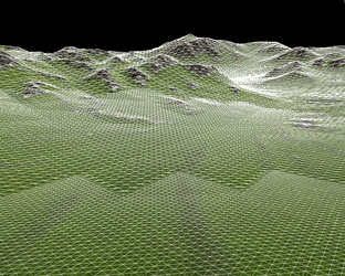
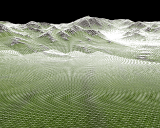
A 1st LOD parameter specifies a distance from the camera to the first LOD that starts a distant-dependent tessellation.
 |
 |
Small LODs distance |
Bigger LODs distance |
Visibility Distance
A Visibility distance sets the range passing which the terrain is no longer rendered. Not the entire terrain disappears at once, but rather starting from the furthest surfaces. If it is set to infinity (inf), there is no distant-dependent optimization for the terrain.
Shadow Distance
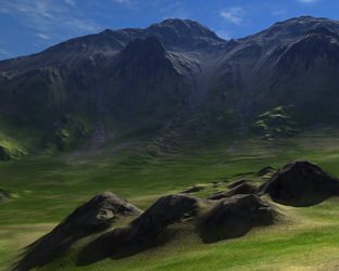
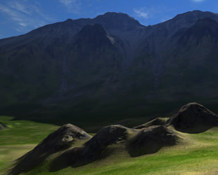
A Shadow distance parameter limits the distance up to which mountains, hills and other terrain relief features cast shadows (Refined -> Cast shadow and Cast world shadows should be enabled for this option to be in effect). If it is set to infinity (inf), shadows will be casted across the whole visible terrain.
 |
 |
Shadow distance = infinity |
Shadow distance = 20 units |
Off-camera shadow extension
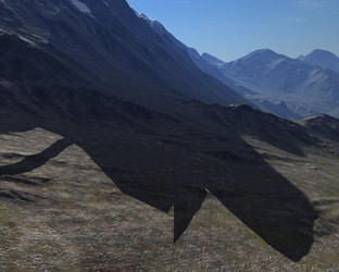
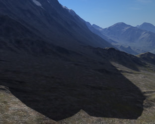
An Off-camera shadow extension is the distance up to which additional terrain polygons outside the viewing frustum are rendered. This option allows eliminating popping of shadows.
When the camera is looking down at the mountain foot, the peaks are outside the viewing frustum and do not cast shadow, though it should be visible. With Off-camera shadow extension parameter, the geometry outside the camera view (in every direction across the chosen distance) is rendered and thus the shadows from mountain tops are in place.
- The shadow radius to set depends on the height of terrain relief features and the angle of the sun (which determines how long the shadows from it would be).
- Set the minimum possible value, as this parameter increases rendering load (check RTriangles counter in the performance profiler).
 |
 |
Radius = 0 |
Radius = 100 units |
Flatness Threshold
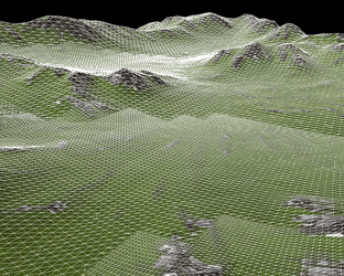
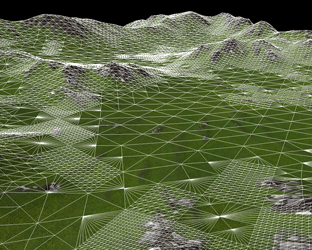
Adaptive tessellation allows you to optimize rendering of plain and flat terrain areas. Instead of subdividing them with a fixed number of steps that the current LOD requires, tessellation adapts to the relief curvature and the viewpoint. The closer to the camera the curvature is and the more prominent it is, the more it gets subdivided. The flatness threshold tests the difference in heights between the polygons in the previous and next coming LOD. It is measured not in units, but in heights gradations.
- The minimum value of 0 means the tessellation is uniform and non-optimized.
- The higher the value, the greater the height difference between the polygons is, and it possible to render polygons as one large patch.
 |
 |
Non-flattened terrain (Flatness = 0) |
Flattened terrain (optimized) |