Generating Vector Objects
Fences, pipes and other such objects are placed along line segments selected from vector data sources (*.shp files).
The basic workflow is as follows:
1. Preparing a Basic Object#
First, we create a basic object, that will be used as a building block for generation - any *.node file containing a single root-node with any hierarchy.
2. Adding a Vector Data Source and Specifying Tags#
This step is the same as Adding a Vector Data Source and Specifying Tags for Spline objects.
3. Specifying Parameters of Vector Objects#
Now, we must add basic objects created at the first step and bind them to the tags created at the second step.
-
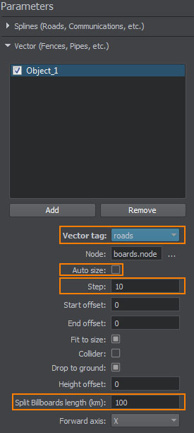
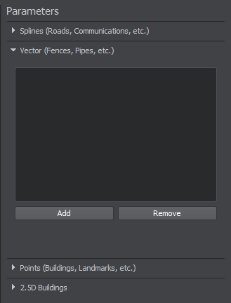
On the Sources panel, select the Vector data source type and the following settings will be displayed in the Vector tab of the Parameters panel.
-
Add a basic object for generation by clicking Add button on the Parameters panel and specify object's name. You can add as many objects as necessary.
-
For each basic object specify the following parameters:

Vector tag The tag to be used for the selected basic object from the list of the tags specified at the second step. Node The path to the basic object's *.node file. Auto size Enables or disables autosize mode for node placement. When this mode is enabled, basic objects are placed with zero-spacing so that bounding boxes of the first and the last basic objects are aligned with start and end points of the line segment respectively. 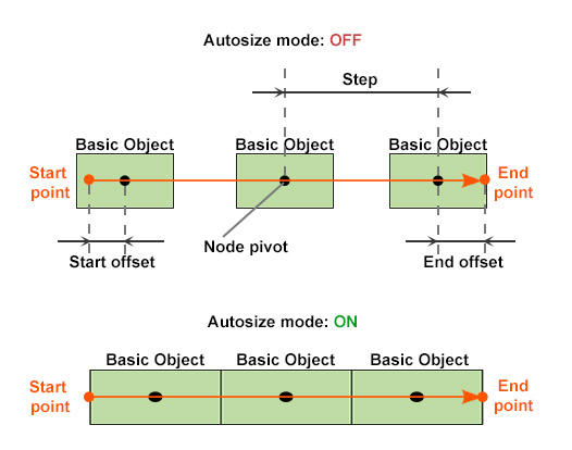
Step Distance between two adjacent basic objects, in units. NoticeAvailable only when autosize mode is disabled.Start offset Offset of the first basic object's pivot from the start point of the line segment, in units. NoticeAvailable only when autosize mode is disabled.End offset Offset of the last basic object's pivot from the end point of the line segment, in units. NoticeAvailable only when autosize mode is disabled.Fit to size Enables stretching/shrinking of basic objects so that they are placed along line segments without spaces between them. NoticeAvailable only when autosize mode is disabled.Collider Flag indicating if collisions for the generated object are to be detected. NoticeAvailable only for geometry type.Drop to ground Flag indicating if the generated object will be aligned with the terrain surface. Height offset Distance from the terrain surface along the Z-axis, in units. NoticeIf you see the generated object partially, You can try to increase this value to lift it above the terrain surface.Bake to cluster Flag indicating if the generated objects will be baked to a MeshCluster. NoticeBaking to a MeshCluster shouldn't be used for large areas because of the coordinates precision limitations.The option is available only when the specified *.node file contains a static mesh.Forward axis Axis along which the basic object is to be tiled: X, -X, Y, -Y. - Check the basic objects you added at the previous step to be generated.
NoticeIf you are going to update some of the existing vector objects, check only the changed ones. At that, the other objects will remain the same after terrain generation.
-
Now all necessary basic objects are specified and bound to tags.
NoticeIf the terrain is already generated and you want to add only vector objects - proceed to Step 4.
Otherwise - return back to setting other parameters of terrain generation.
4. Generating Vector Objects#
Now you can generate vector objects by clicking Generate button and selecting Vector objects option in the Steps window, in this case only vector objects will be generated.
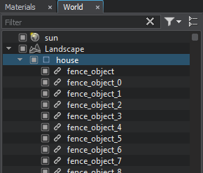
By default, the generated houses are added to the world hierarchy as NodeReferences. However, it can be baked to a MeshCluster.
 |
 |
Vector Objects as NodeReferences |
Vector Objects as MeshCluster |
To regenerate some of the existing vector objects, check only those objects that should be updated, click Generate and select Vector objects option. Only the specified vector objects will be regenerated. At that, the other ones (that haven't been checked) will remain the same.
Placing Billboards#
You can also place billboards along the line segments selected from vector data sources.

This option can be used, for example, to simulate lights along the generated roads. The basic workflow is the same as described above with the following additions:
- At Step 1 you should use a *.node file containing a single Billboards object as the basic object. The Billboards object should contain a single billboard and have an emissive material assigned to its surface. NoticeIf a *.node file contains several billboards, only the settings of the first one will be used.
- Step 2 can be skipped, as you will use the same tag as for generated roads along which the lights are to be placed.
-
At Step 3 when specifying parameters you should do the following:
- In the Tag field you should select the same tag as for generated roads along which the lights are to be placed.
- Disable the Autosize option
- Set the value for the Step parameter that determines the distance (in units) between the two adjacent lights (billboards) placed along the road.
You will have an extra parameter available - Split Billboards length (km). This parameter allows you to control the number of Billboards objects that will be generated due to area splitting:
- low values will increase the number of generated Billboards objects
- high values will reduce this number
NoticeThe maximum number of billboards contained in a single Billboards object is limited to 8000.
Thus, the number of generated Billboards objects is also affected by the Step value, that you specify, since a low value produces a large total number of billboards.
Although billboards are performance-friendly, generating too many of them may reduce performance.