在连接的导航扇区内创建路线
 The example guides you through the process of setting up a scene with a navigation area of a complex form and calculating 2D and 3D routes within it.该示例指导您通过设置具有复杂形式的导航区域的场景并在其中计算2D和3D路线的过程。
In UNIGINE, only Navigation Sectors can be used for calculation of both 2D and 3D routes. The navigation sectors can be easily rearranged, disabled, or enabled on the fly. Moreover, you can specify the sectors that can participate in pathfinding and exclude others. In order to form a unified navigation area, the sectors must intersect with each other.在UNIGINE中,只有Navigation Sector可用于2D和3D路线的计算。 导航扇区可以很容易地重新排列、禁用或启用。 此外,您可以指定参与寻路的扇区,并排除其他扇区。为了形成统一的导航区域,扇区之间必须相互相交。
Let's consider these features in detail.让我们详细分析这些特性。
Preparing Scene准备场景#
Our scene will include a navigation area that consists of multiple intersecting navigation sectors and primitives indicating the start and destination points of a route.我们的场景将包括一个导航区域,该区域由多个相交的导航扇区和指示路线起点和目的地点的图元组成。
- Create an empty C# project via SDK Browser.通过SDK Browser创建一个空的C#项目。
- Open it in UnigineEditor and remove the unnecessary default nodes.在UnigineEditor中打开它并删除不必要的默认节点。
-
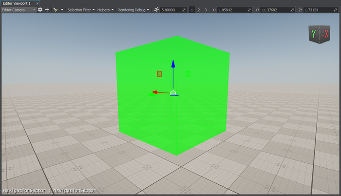
In the Menu bar, choose Create -> Navigation -> Navigation Sector and place the node above the plane.在菜单栏中,选择Create -> Navigation -> Navigation Sector并将节点放在平面上方。注意To facilitate working with the navigation sectors, activate gizmos for Navigation nodes in the Helpers Panel.为了便于使用导航扇区,请在Helpers面板中为Navigation节点激活小控件。
-
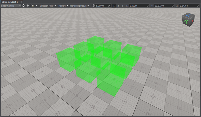
Add 8 more navigation sectors to the scene by cloning (Ctrl+D) the existing sector and place them as follows:通过克隆(Ctrl+D)现有扇区,在场景中添加8个导航扇区,并将其放置如下:注意You can position the sectors manually using manipulators or by specifying the exact position via the Parameters window.您可以使用操纵器或通过Parameters窗口指定精确位置手动定位扇区。
- In the Parameters window, adjust the positions of the nodes along the Z axis so that they are all positioned at the same level above the plane.在Parameters窗口中,沿Z轴调整节点的位置,使它们都位于平面上方的同一水平。
-
Add a new sector and adjust its Size in the Parameters window to give it a parallelepiped shape.添加一个新扇区并在Parameters窗口中调整其Size,使其具有平行六面体形状。
 注意At this step, you can approximately set the size of the sector. However, you may need to adjust it later to prevent excluding the navigation sector from pathfinding.在这一步,可以近似地设置扇区的大小。 但是,您可能需要稍后进行调整,以防止将导航扇区排除在寻路之外。
 -
Connect the cuboid-shaped navigation sectors: place the new sector between them.连接长方体形状的导航扇区:将新扇区置于它们之间。
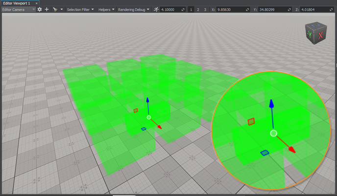 注意For 2D routes, the height difference between the intersecting sectors must not exceed the maximum height set for the 2D route; otherwise, these sectors are discarded from pathfinding. In addition, the intersection area must exceed the radius and height of the route. So, it may be necessary to adjust the size and position of the sector to correct the intersection area.对于2D路由,相交扇区之间的高度差不得超过为2D路由设置的最大高度;否则,从寻路中丢弃这些扇区。 此外,交叉区域必须超过路线的半径和高度。 因此,可能需要调整扇区的大小和位置以校正相交区域。
 -
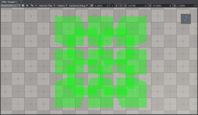
Add 11 more navigation sectors that connect the cuboid-shaped sectors by cloning (Ctrl+D) the existing sector and place them as follows:通过克隆(Ctrl+D)现有扇区,再添加11个连接长方体形状扇区的导航扇区,并将其放置如下:
-
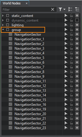
Organize the created navigation sectors in a hierarchy. It will allow you to manage the navigation area as a single node. Select all the navigation sectors, right-click, and choose Group in the drop-down list or press Ctrl+G.在层次结构中组织创建的导航扇区。 它将允许您将导航区域管理为单个节点。 选择所有导航扇区,右键单击,并在下拉列表中选择Group或按Ctrl+G。
-
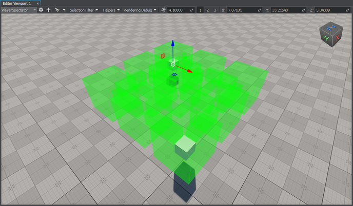
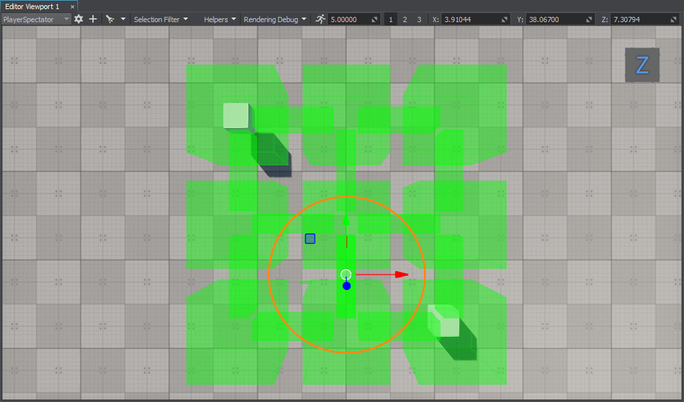
Add 2 nodes to be used as the start and destination points of the route. We will create 2 boxes (Create -> Primitives -> Box), rename them start and finish, and then place them inside the navigation sector as pictured below.添加2个节点用作路由的起点和终点。 我们将创建2个平行六面体(Create -> Primitives -> Box),将它们重命名为start和finish,然后将它们放置在导航扇区中,如下图所示。
Creating Component for 2D Route Calculation创建用于2D路径计算的组件#
The created navigation sectors only provide the area within which routes are calculated. The routes themselves should be created from the code. So, let's create the corresponding C# component for 2D route calculation:创建的导航扇区仅提供计算路线的区域。 路由本身应该从代码中创建。 因此,让我们2D路由计算创建相应的C#组件:
If you have completed the previous guide on creating routes within a simple navigation sector, you can skip this step and copy the implemented Route2D.cs component to the data/components folder of your project.如果您已经完成了上一篇关于在简单导航扇区中创建路由的指南,则可以跳过此步骤并将实现的Route2D.cs组件复制到项目的data/components文件夹中。- Create the components folder in the data directory of your project: right-click in the Asset Browser and select Create Folder.在项目的data目录中创建components文件夹:在资源浏览器中右键单击并选择Create Folder。
-
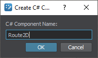
In the created folder, create a new component: right-click and select Create Code -> C# Component and specify a name for the component.在创建的文件夹中,创建一个新组件:右键单击并选择Create Code -> C# Component并为组件指定一个名称。
- Open the component in IDE to implement pathfinding logic.在IDE中打开组件实现寻路逻辑。
Implementing Component Logic实现组件逻辑#
If you have copied the Route2D.cs component on the previous step, you can skip this one.如果您在上一步复制了Route2D.cs组件,则可以跳过此步骤。-
Declare component parameters:声明组件参数:
- Two parameters that will accept nodes between which a route should be calculated两个参数将接受应该计算路由的节点
- Route color路线颜色
源代码 (C#)public class Route2D : Component { // a node that will serve as a start point public Node startPoint = null; // a node that will serve as a destination point public Node finishPoint = null; // route color [ParameterColor] public vec4 routeColor = vec4.ZERO; // ... } -
Create a route and set the radius and height that required to move the point along the route in the Init() method. Before creation, check if the nodes to be used as the start and finish points are specified.创建一条路线,并设置在Init()方法中沿着路线移动点所需的半径和高度。 在创建之前,检查是否指定了要用作起点和终点的节点。注意Choosing the radius and height values is essential. If the height or radius exceeds the size of the sector or the intersection area, such sector/area will be excluded from pathfinding. To address this, you can modify the route parameters or adjust the size of the sector or intersection area.选择半径和高度值至关重要。 如果高度或半径超过扇区或交叉区域的大小,则此类扇区/区域将被排除在寻路之外。 为了解决这个问题,您可以修改路线参数或调整扇区或交叉区域的大小。源代码 (C#)
// a route private PathRoute route = null; private void Init() { // check if the start and destination nodes are correctly specified via the component interface if (startPoint && finishPoint) { // create a new route route = new PathRoute(); // set a radius and height for the point which will move along the route route.Radius = 0.1f; route.Height = 0.1f; } } -
To enable displaying the calculated route at run time, turn on the Visualizer. Additionally, you can output console messages to the application screen. Add the following logic to the Init() function:要启用在运行时显示计算的路由,请打开Visualizer。 此外,您还可以将控制台消息输出到应用程序屏幕。 将以下逻辑添加到Init()函数中:源代码 (C#)
// enable the onscreen console messages to display info on route calculation Unigine.Console.Onscreen = true; // enable visualization of the calculated route Visualizer.Enabled = true; -
In the Update() function, calculate the route from the start to destination node:在Update()函数中,计算从起点到目的节点的路由:源代码 (C#)
private void Update() { // check if the start and destination nodes are correctly specified via the component interface if (startPoint && finishPoint) { // calculate the path from the start to destination point // a destination point of the route is reached route.Create2D(startPoint.WorldPosition, finishPoint.WorldPosition); if (route.IsReached) { // if the destination point is reached, render the root in a specified color route.RenderVisualizer(routeColor); } else Log.Message($"{node.Name} PathRoute not reached yet\n"); } } -
Implement the Shutdown() function to disable the visualizer and onscreen console messages:实现Shutdown()函数以禁用可视化工具和屏幕控制台消息:源代码 (C#)
private void Shutdown()
{
	Unigine.Console.Onscreen = false;
	Visualizer.Enabled = false;
}
Here is the full code of the component:下面是组件的完整代码:
Route2D.cs
using System.Collections;
using System.Collections.Generic;
using Unigine;

[Component(PropertyGuid = "AUTOGENERATED_GUID")] // <-- this line is generated automatically for a new component
public class Route2D : Component
{
	// a node that will serve as a start point
	public Node startPoint = null;
	// a node that will serve as a destination point
	public Node finishPoint = null;

	public bool visualizeRoute = false;
	// route color
	[ParameterColor]
	public vec4 routeColor = vec4.ZERO;
	// a route
	private PathRoute route = null;

	private void Init()
	{
		// check if the start and destination nodes are correctly specified via the component interface
		if (startPoint && finishPoint)
		{
			// create a new route
			route = new PathRoute();

			// set a radius and height for the point which will move along the route
			route.Radius = 0.1f;
			route.Height = 0.1f;
			// enable the onscreen console messages to display info on route calculation
			Unigine.Console.Onscreen = true;
			// enable visualization of the calculated route
			Visualizer.Enabled = true;
		}
	}
	private void Update()
	{
		// check if the start and destination nodes are correctly specified via the component interface
		if (startPoint && finishPoint)
		{
			// calculate the path from the start to destination point
			// a destination point of the route is reached
			route.Create2D(startPoint.WorldPosition, finishPoint.WorldPosition);
			if (route.IsReached)
			{
				// if the destination point is reached, render the root in a specified color
				if (visualizeRoute)
					route.RenderVisualizer(routeColor);
			}
			else
				Log.Message($"{node.Name} PathRoute not reached yet\n");
		}
	}

	private void Shutdown()
	{
		Unigine.Console.Onscreen = false;
		Visualizer.Enabled = false;
	}
}
Assigning Component分配组件#
When the component logic is implemented, you should assign it to a node.实现组件逻辑时,应将其分配给节点。
- In UnigineEditor, select Create -> Node -> Dummy and place it in the navigation area.在UnigineEditor中,选择Create -> Node -> Dummy并将其放置在导航区域中。
- Select the dummy node and assign the Route2D.cs component to it in the Parameters window.选择虚拟节点并在Parameters窗口中将Route2D.cs组件分配给它。
-
In the component parameters, specify the start and finish static meshes in the Start Point and Finish Point fields.在组件参数中,在Start Point和Finish Point字段中指定start和finish静态网格体。
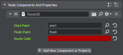
- Change the Route Color, if necessary.如有必要,请更改Route Color。
Visualizing Navigation Area可视化导航区域#
To clearly show how the path is built inside the navigation area, let's implement the AreaVisualizer component that enables displaying the navigation area gizmo at run time:为了清楚地显示路径是如何在导航区域内构建的,让我们实现AreaVisualizer组件,该组件允许在运行时显示导航区域小工具:
-
In the components folder, create the AreaVisualizer component.在components文件夹中,创建AreaVisualizer组件。注意If you have completed the previous guide on creating routes within a simple navigation sector, you can skip this step and use the implemented AreaVisualizer component. Just copy it to the data/components folder of your project and assign it to all the navigation sectors forming the navigation area.如果您已经完成了上一篇关于在简单导航扇区中创建路由的指南,则可以跳过此步骤并使用实现的AreaVisualizer组件。 只需将其复制到项目的data/components文件夹中,并将其分配给构成导航区域的所有导航扇区。
-
Implement rotation logic:实现旋转逻辑:源代码 (C#)
public class AreaVisualizer : Component { private NavigationSector navigationSector = null; private void Init() { // get the navigation sector to which the component is assigned navigationSector = node as NavigationSector; // enable rendering of the visualizer if (navigationSector) Visualizer.Enabled = true; } private void Update() { // display the navigation area gizmo if (navigationSector) navigationSector.RenderVisualizer(); } private void Shutdown() { // disable rendering of the visualizer Visualizer.Enabled = false; } } - Assign the component to each navigation sector forming the navigation area.将组件分配给形成导航区域的每个导航扇区。
Trying Out尝试#
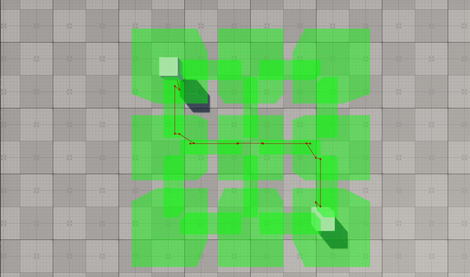
Click Run to run the component logic and check the result.单击Run以运行组件逻辑并检查结果。
If the route is not reached, try to modify the route parameters (a point height and/or radius) or adjust the size of the sector(s) or intersection area(s), as the point moving along the route must fit the size of the navigation area.如果未到达路线,请尝试修改路线参数(点高度和/或半径)或调整扇区或交叉区域的大小,因为沿着路线移动的点必须适合导航区域的大小。
Excluding Sectors from Pathfinding从寻路中排除扇区#
Sometimes, it might be necessary to ignore some navigation sectors during pathfinding. For this purpose, you can set the Navigation mask for both the navigation sector and the route so that they don't match.有时,可能需要在寻路过程中忽略某些导航扇区。 为此,您可以为导航扇区和路线设置Navigation掩码,以便它们不匹配。
-
Select one of the navigation sectors participating in pathfinding.选择参与寻路的导航扇区之一。
-
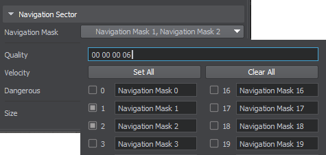
Change its Navigation Mask in the Parameters window.在Parameters窗口中更改其Navigation Mask。
-
Run the application to check how the route is recalculated.运行应用程序以检查路由是如何重新计算的。
Modifying Component for 3D Route Calculation修改三维路径计算组件#
The navigation sector also enables the calculation of 3D routes, with some features that differ from the 2D routes:导航部分还可以计算3D路线,具有与2D路线不同的一些特征:
- For 3D routes, the point moves in 3 dimensions.对于3D路线,点在3维中移动。
- Only the radius set for the point matters: if the radius set for the point is greater than the size of the navigation sector, it will be discarded.只有为点设置的半径才重要:如果为点设置的半径大于导航扇区的大小,它将被丢弃。
- The maximum height set for the route determines the upper limit of the point's vertical movement.为路线设置的最大高度确定点垂直移动的上限。
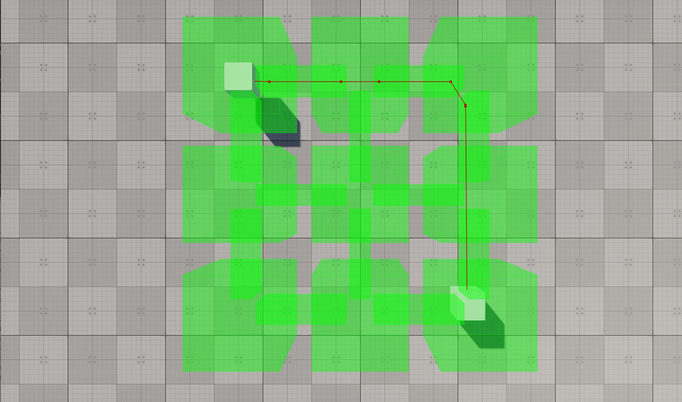
You can force the Route2D component to calculate a 3D route within the same navigation area by changing a single line of the code. Replace the route.Create2D() function call with the following:您可以通过更改代码的单行来强制Route2D组件计算同一导航区域内的3D路线。 将route.Create2D()函数调用替换为以下内容:
route.Create3D(startPoint.WorldPosition, finishPoint.WorldPosition);Run the application to check the result.运行应用程序以检查结果。
本页面上的信息适用于 UNIGINE 2.19.1 SDK.