Setting Up Cameras
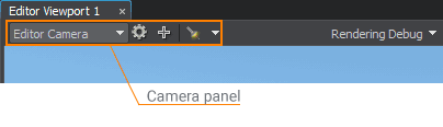
The main camera functions are available via the Camera panel of the Editor Viewport: you can switch between cameras, add new cameras to the current world, open the Camera Settings window, and toggle the flashlight attached to the camera.
By default, there are 2 cameras in the world:
- Engine Camera created from the world script. The view from this camera is rendered in a separate Engine Viewport, and you cannot change its settings via UnigineEditor. This camera represents the current player. Engine Camera can be changed via the script.
-
Editor Camera created from the editor script. This is the default camera in UnigineEditor.
NoticeBoth Engine Camera and Editor Camera always exist in the world.
You can also add new cameras. Such cameras can be used as watchpoints in the world: you can position cameras at different points of the world and then switch between them via the Camera panel of the Editor Viewport, when necessary.
Adding a New Camera#
To add a new camera to the current world:
-
Change the position and orientation of the current camera by using the navigation controls.
NoticePosition, orientation, and settings of the current camera are copied for the new camera. -
On the Camera panel, click
 . A new camera will be added to the list of the available cameras with the PlayerDummy name.
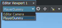 A new available camera
At the same time, the camera will be added to the world as a PlayerDummy node.
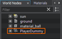 A new PlayerDummy node
 - Change the default camera settings to the required ones.
Positioning the Camera#
To set a new position and orientation for the camera, place the camera to the required position and adjust its orientation as necessary by using the navigation controls.
You can also position the camera by selecting it in the World Hierarchy window and directly changing its transformation via the Parameters window.
Setting Up the Camera#
As settings of a new camera are simply copied from the current camera, you may need to change them via the Camera Settings window.
To open the Camera Settings window, choose the required camera and click ![]() on the Camera panel.
on the Camera panel.
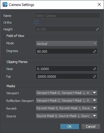
Camera Settings#
The list of available camera settings depends on the camera mode:
- Perspective mode
- Orthographic mode
|

|
|
Perspective Camera Settings
|
Orthographic Camera Settings
|
| Option | Description | ||||
|---|---|---|---|---|---|
| Name | Name of the current camera. If you change the camera name, the name of the node (PlayerDummy) will be also changed. | ||||
| Ortho |
Toggles between the perspective and orthographic camera modes.
|
||||
| Height |
Height of the viewing volume which is represented in the form of a rectangular parallelepiped. The width of the viewing volume will be equal to its height. Notice
The option is available only in the orthographic camera mode (the Ortho option is checked). |
||||
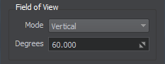
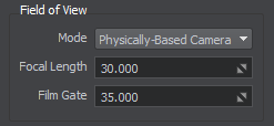
| Field of View (available only for the perspective mode) | |||||
| Mode |
FOV mode. The available values are:
|
||||
| Degrees |
Camera's vertical field of view in degrees. This is the area that can be seen in the viewport (how many degrees the camera covers). Notice
Available for the camera with the vertical FOV only. |
||||
| Focal Length |
The focal length of the physically-based camera lens. Notice
Available for the physically-based camera only. |
||||
| Film Gate |
The film gate for the physically-based camera with horizontal FOV. Notice
Available for the physically-based camera only. |
||||
| Clipping Planes | |||||
| Near | Distance to the camera near clipping plane. | ||||
| Far | Distance to the camera far clipping plane.
Notice
An extremely big difference between the Near and Far Clipping Planes can cause black screen. Therefore, if the required Far Clipping Plane value is outside the range, adjust the Near Clipping value proportionately. |
||||
| Masks | |||||
| Viewport | A viewport bit mask for the camera that enables to selectively display objects, decals and lights in the camera viewport. If at least one bit matches, the object, decal or light will be rendered. The mask can be edited. | ||||
| Reflection Viewport | A viewport bit mask for the reflection camera that enables selective display of reflections from objects. The mask can be edited. | ||||
| Reverberation | A reverberation mask for the camera determines what reverberation zones can be heard. At least one bit of this mask should match the reverb mask of the sound source and the reverb mask of the reverberation zone. The mask can be edited. | ||||
| Sound | A sound mask for the camera that what sound channels can be heard. If at least one bit matches the sound source mask, the sound can be heard. Each bit of the source mask specifies a sound channel. The mask can be edited. | ||||
Rendering the Camera Viewport in a Separate Window#
The view from each camera can be rendered into a separate Editor Viewport window.
To render a view from a camera to a separate viewport, perform the following steps:
-
Add a new Editor Viewport window, choose Windows -> Add Editor Viewport.
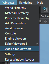
A new viewport named Editor Viewport 2 will open.
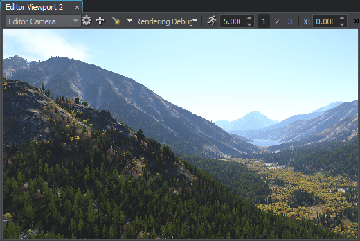 New Editor Viewport
 -
Select the required camera to render the view from in the drop-down list of the Camera panel.
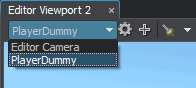 NoticeYou can change the camera at any time, if necessary.
The total number of viewports that can be opened simultaneously is not limited. Each new viewport window has the same functionality as the main Editor Viewport window.
You can use several Editor Viewports to operate with several nodes located far away from each other, or to view different orthographic projections of the scene (Top, Front, and Side views).
Hiding and Showing Viewports#
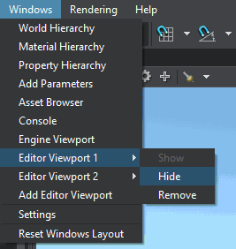
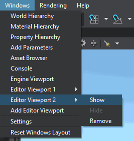
You can hide the Editor Viewport window and show the one that is hidden. To toggle the Editor Viewport window, select its name in the Windows menu and choose Show or Hide.
|
|
|
Hide the Editor Viewport 1
|
Show the Editor Viewport 2
|
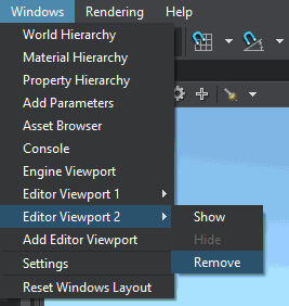
Removing Viewports#
You can remove an Editor Viewport window when you no longer need one. To do so, select the name of the Editor Viewport, that you want to remove in the Windows menu and choose Remove.