Terrain
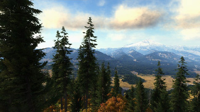
A terrain is the most important object in the outdoor scene rendering. Unigine provides an opportunity to create limitless terrains with naturally diverse features:
- Plain or hilly relief based on imported or created with Terrain Editor height maps
- Realistic surface coverings (grass, rocks, dirt) created by means of terrain layers
- Holes based on imported or created with Terrain Editor holes map
The terrain object is a regular 2D grid with the specified step. It has the assigned 32-bit height map with the following bits usage:
- The height is stored with the 31-bit precision, which provides up to 2^31 height levels
- 1 bit is used to indicate whether there is a hole in it or not
See Also
- A Terrain Materials article for information about terrain materials
- A Terrain Editor tool for changing the terrain relief and color
- A Terrain Grabber tool for current terrain textures baking
- A terrain_base material that is applied to terrains
- An ObjectTerrain class to edit terrains via C++, C# or UnigineScript API.
Creating a Terrain
To create a new flat terrain with the specified dimensions via UnigineEditor, do the following:
- Run UnigineEditor.
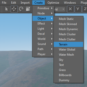
- On the Menu bar, click Create -> Object -> Terrain.
- In the dialog window that opens, specify the following parameters:
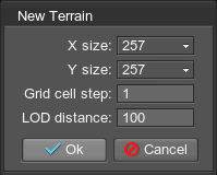
Name Description X size
Y sizeTerrain dimensions along the X and Y axes (i.e. how many grid cells there are along the X and Y axes). For example, if both parameters are set to 256, the terrain will have 16×16 grid cells. Grid cell step The step of a grid cell, in units. It determines how many times the terrain grid cell will be bigger than the default one (equal to one unit). At the picture below, both terrain have the same 256x256 dimensions, the step of the first terrain is equal to 1 unit, of the second to 2. 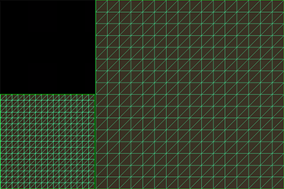 NoticeThe parameter does not affect the storage size of the terrain, it just enlarges the terrain grid cell, so the amount of triangles remains the same.
LOD Distance The distance to the first LOD that starts the distant-dependent tessellation. NoticeThe terrain dimensions and grid step cannot be changed afterwards. - Choose the path to the existing .terrain file to overwrite it, or choose the path to the new terrain.
- Place the terrain somewhere in the world.
Terrain Parameters
Terrain Size
The size of the terrain is calculated as (power of two + 1) × (power of two + 1), which is equal to the total count of terrain vertices.
- The maximum size of a terrain is 32769 × 32769
- The minimum size of a terrain is 257 × 257
A terrain dimension along the axis is determined by the (Cells count - 1) * Grid cell step formula.
X size, Y size, Grid cell step and Max height parameters determine the maximum slope angle, i.e. the number of vertices at a given relative altitude. The bigger the grid sizes, the smaller the step and the height, the steeper the terrain slope can be. However, sometimes it is more rational to create very steep cliffs with a separate mesh rather than to set very high density of a terrain grid.
Terrain File Format
-
 data
data
-
 src_project
-
 materials
 -
 meshes
-
 buildings
 -
 vegetation
 -
 vehicles
-
-
 nodes
nodes
-
 buildings
 -
 vegetation
 -
 vehicles
-
-
 textures
-
 buildings
 -
 vegetation
 -
 vehicles
-
-
-
Terrain data is stored in the following formats:
- .ter file stores the meta information about a terrain object, such as bounding box of terrain, bounding boxes of surfaces and whether they are enabled or disabled. It also stores vertices of a coarse level.
- .terxxxx files store information about heights in terrain surfaces (up to 8×8 maximum), as well as information about holes.
Terrain textures data is stored in the following formats:
- _d.dds - coarse albedo map
- _n.dds - coarse normal map
- _m.dds - coarse mask texture
- 00x00_x.dds - per-surface albedo, normal and mask textures. They are stored in a separate folder that is named after the terrain file.
Terrain Physics Simulation
The terrain takes part in physics simulation if it has a standard surface_base property assigned. Collisions with physical bodies use the most detailed LOD 0 and are handled within a set distance, where simulation of physics is in effect.
Terrain Textures
All of the textures have the following requirements:
| Size | (power of two + 1) × (power of two + 1) pixels
|
|---|---|
| Import Formats |
|
| Export Formats |
Notice
For height, holes, albedo, normal and mask textures only. |
Terrain Textures Arrays
When you add a new layer and load textures for layer, the engine automatically generates arrays of albedo, normal and height textures. Arrays consist of textures of all layers.
The size of arrays can be changed manually in the Layers tab.
Textures Compression
After loading of all the textures and finishing their editing in Terrain Editor, it is strongly recommended to compress them for more efficient usage of the memory. The Compress option compresses refined albedo, normal, and mask textures, as well as their coarse textures. Layer textures are not compressed.

The following conversion is done:
- R8 to ATI1
- RG8 to ATI2
- RGB8 to DXT1
- RGBA8 to DXT5
On the contrary, the Decompress option decompresses all compressed textures mentioned above.
Textures Export
You can export any of your basic textures via the Export tab. Just press Export near the required texture. In the opened dialog window choose the extension and a path to the texture.
For a height map, you need to specify a Max Height parameter, which is equal to the terrain maximum height.

Terrain Optimizations
A level of details (LOD) system automatically adapts the density of a terrain grid detailing according to the distance. There are two types of visibility levels that depend on the distance:
- A coarse level is the furthermost from the camera and the least detailed. On this level coarse albedo, normal and mask textures are rendered. They are always stored in the memory and allow renderer to effectively render extremely large terrains.
- A refined level is closer to the camera and more detailed. When a terrain is created, its grid is automatically divided into smaller refined chunks of 257×257 vertices in size (shown in the Refined tab). Each surface has a unique set of textures, which, in fact, are parts cut out from the imported textures. Parameters of each surface can be modified either together or separately.
LODs Tessellation
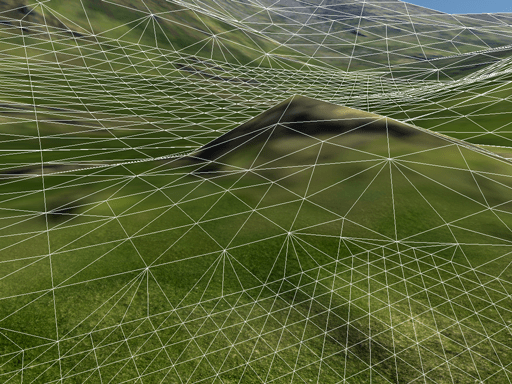
Terrain LOD system has smoothly adapting tessellation required to avoid seams and cracks in transition regions. Each vertex near the outer perimeter of a smaller LOD is seamlessly stitched to the neighboring polygons of a bigger LOD with additional triangles. The same technique is used to smoothly fuse heights and holes into the terrain.
Geomorphing
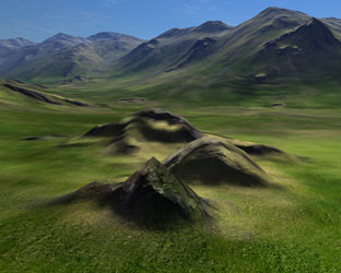
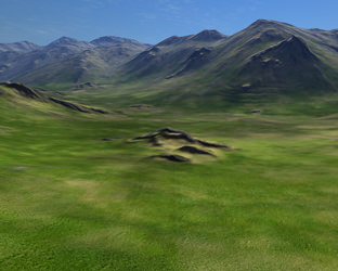
Another problem of switching between two tessellation levels is popping of vertices. For example, when polygons that form pyramid-like bump are abruptly switched to one flat polygon, it gives a very unpleasant popping effect. Geomorphing technique introduces an effective way out: before actually switching to the next LOD, it smoothly moves vertices down to their position, morphing the bump into flat surface. As a result, there are no artifacts visible; even in case of a very sparse grid and too small LOD distance only slightly moving vertices can be noticed.
|
|
|
Hummock from close-by
|
The same hummock from further away
|
Refined Textures
When a terrain is created, its grid is automatically divided into smaller refined chunks of 257×257 vertices in size (shown in the Refined tab). Each surface has a unique set of textures, which, in fact, are parts cut out from the imported textures.
You can modify the following parameters in the Refined tab:
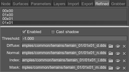
- Enabled - enable or disable the terrain chunk.
- Cast shadow - cast the shadows from the chunk terrain relief.
- Threshold - the flatness threshold for the chunk.
- Albedo - the albedo texture of the chunk.
- Normal - the normal texture of the chunk.
- Mask - the mask of the chunk.
You can manually change a size of refined albedo, normal and mask textures in the Texture Resolution field of the Parameters tab.

Paths to the refined albedo, normal, mask textures is displayed at the File Structure field.

Coarse Textures
Coarse albedo, normal, mask textures are generated automatically and are shown in the Coarse Texture field of the Parameters tab.

You can manually change a size of coarse albedo, normal and mask textures in the Texture Resolution field of the Parameters tab.

LODs Settings
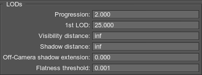
You can modify the following LODs parameters in the LODs field of the parameters tab:
- Progression - a coefficient to calculate the distances from the first LOD to other LODs.
- 1st LOD - the first level of details.
- Visibility distance - the terrainvisibility distance.
- Shadow distance - the distance up to which a terrain relief casts shadows.
- Flatness threshold - a flatness threshold.
1st LOD
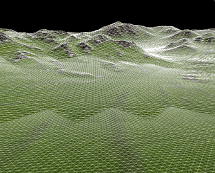
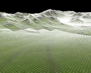
A 1st LOD parameter specifies a distance from the camera to the first LOD that starts a distant-dependent tessellation.
|
|
|
Small LODs distance
|
Bigger LODs distance
|
Visibility Distance
A Visibility distance sets the range passing which the terrain is no longer rendered. Not the entire terrain disappears at once, but rather starting from the furthest surfaces. If it is set to infinity (inf), there is no distant-dependent optimization for the terrain.
Shadow Distance
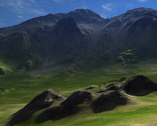
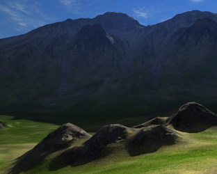
A Shadow distance parameter limits the distance up to which mountains, hills and other terrain relief features cast shadows (Refined -> Cast shadow and Cast world shadows should be enabled for this option to be in effect). If it is set to infinity (inf), shadows will be casted across the whole visible terrain.
|
|
|
Shadow distance = infinity
|
Shadow distance = 20 units
|
Flatness Threshold
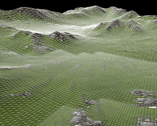
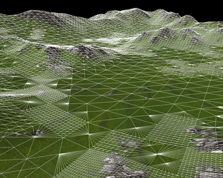
Adaptive tessellation allows you to optimize rendering of plain and flat terrain areas. Instead of subdividing them with a fixed number of steps that the current LOD requires, tessellation adapts to the relief curvature and the viewpoint. The closer to the camera the curvature is and the more prominent it is, the more it gets subdivided. The flatness threshold tests the difference in heights between the polygons in the previous and next coming LOD. It is measured not in units, but in heights gradations.
- The minimum value of 0 means the tessellation is uniform and non-optimized.
- The higher the value, the greater the height difference between the polygons is, and it is possible to render polygons as one large patch.
|
|
|
Non-flattened terrain (Flatness = 0)
|
Flattened terrain (optimized)
|