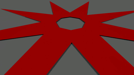
Mesh Clutter
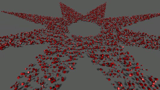
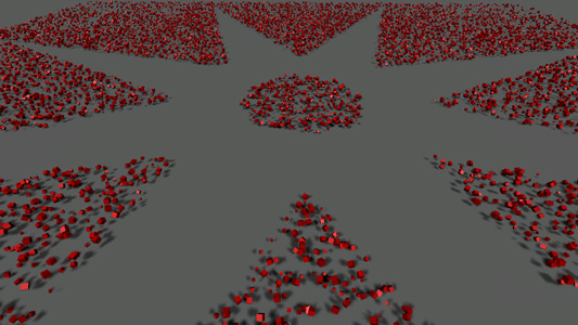
Mesh Clutter is an object that can contain a great number of identical meshes which are positioned, oriented and scaled randomly and cannot be managed manually. Meshes of the Mesh Clutter object can be scattered in the certain areas by using an image or mesh mask.
The Mesh Clutter object is usually used for vegetation (for example, forest, leaves on the ground), for strewing identical objects (for example, rubbish).
Mesh Clutter is used to scatter identical meshes across the world (or the part of the world) or terrain. Mesh Clutter scatters objects procedurally, and renders only those objects which are in the viewing frustum. This allows to render the large number of meshes while keeping performance high.

See also#
- The ObjectMeshClutter class to edit clutters via API
- The Clutter sample located in the Art Samples suite:
Creating Mesh Clutter#
To create Mesh Clutter, simply perform the following steps:
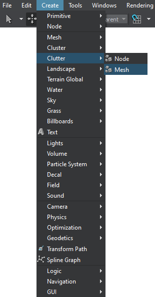
- On the Menu bar, click Create -> Clutter -> Mesh.
- In the dialog window that opens, choose the path to the .mesh file. This mesh would be used as the source one for the Mesh Clutter.
- Place the Mesh Clutter object somewhere in the world.
- Specify the Mesh Clutter parameters.
Mesh Clutter Parameters#
The Mesh Clutter is very much the same as World Clutter (that operates on different node references). It is rendered as a 2D grid, in each cell of which a number of meshes are randomly placed depending on the Mesh Clutter density and probability of appearing. The cells are generated one by one starting from the nearest ones. This approach allows to control how close or far the scattered objects are from each other and at the same time reduce the rendering load when the camera moves and farther cells become visible.
| Mesh | Mesh, the copies of which will be scattered. |
|---|---|
|
Size X
Size Y |
The size of the Mesh Clutter bounding box along X and Y axis. Within this area objects will be scattered with specified density.
|
| Step for cells |
Cell size in units. The resulting number of cells in the Mesh Clutter is defined in the following way: size of the Mesh Clutter (both along X and Y) is divided by the step.
|
| Density | Density specifies how many objects there are per square unit.
|
| Visibility distance |
Across the visibility distance the number of objects is strictly specified by the Density parameter. It means that all objects that should be present are found in place.
|
| Fade Distance | Across the fade distance the number of objects gradually decreases, as they disappear randomly one by one. Fade distance is measured starting from the Visibility Distance. If fade distance is set, there is no clear line where the meshes abruptly disappear. Instead, a few of them will be left smoothly blend into the background without any visual noise.
Notice
For the best result, it is also recommended to combine this effect with objects fade-out. |
| Seed | The seed value for pseudo random number generator allows to create different patterns of automatic positioning. The seed is either be set manually or an engine provides a random value for a seed (Randomize option). |
Randomizing Clutter Objects#
To randomize the appearance of meshes scattered by Mesh Clutter, two types of values are used:
- Mean value (i.e., Scale, Offset, Rotation) defines the average value. This is the basic value that will be randomly made higher or lower.
- Spread value defines the range for possible variation of the parameter. The higher the value, the more diverse the final result will be.
Spread value isoptional: if set to 0, it will not influence the simulation process and only the mean value will be used for all objects.
After these values are specified, each parameter is calculated according to the following formula:
Result = Mean + Random * Spread,
where Random is a random value in range from -1 to 1. For example, if a mean value of the parameter equals 3 and a spread value equals 1, the final result will be any in range from 2 to 4.
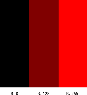
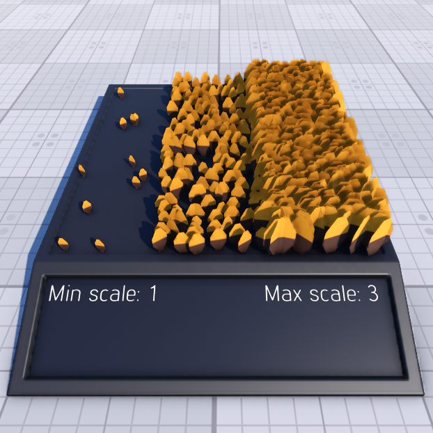
| Min and Max Scale | The scale mean value of scattered objects depends on the minimum and maximum scale mean values and the image mask values: the mask values are used for linear interpolation between the minimum and maximum scale values.
For example, if the following image mask is used:
The Mesh Clutter objects will be scaled as follows:
|
||||||||
|---|---|---|---|---|---|---|---|---|---|
| Offset | Height offset parameter controls whether all objects are positioned at one height or some are found higher or lower. For example, with offset stones can be dug deep into the ground so that only a small top part is visible, or placed higher and look bigger.
|
||||||||
| Rotation X Rotation Y Rotation Z |
These parameters allow to randomly orient the scattered objects.
|

Masking Areas with Objects#
Besides scattering the meshes evenly across the whole area, a mask for their positioning can be used. It controls where the meshes should be placed.
| Image Mask |
Mask determines areas across which the objects are randomly scattered and areas where there will be no objects from the list. For example, on the terrain a mask allows to scatter stones across the rocky areas, while leaving the grassy ones free from rocks. Notice
Notice
To paint the image mask directly in the scene, use Mask Editor. |
|---|---|
| Threshold for mask | To control the strength of masking, a mask threshold is used. It checks the masked density for an area and if a threshold value is higher than the color value of the mask, objects are scattered across it. If the masked density is not enough, the places is left bare.
|
| Terrain Mask | Mask of the Landscape Terrain to be used to define the area where the Mesh Clutter object is to be placed. |
| Mesh Mask | A mesh-based mask can be used to place the objects. Vector masking makes it possible to create roads, rivers, etc. with extremely high precision regardless of the mask texture resolution. A mesh for masking should be a simple planar mesh.
Mesh used as a mask
Mesh-based masking
|
| Inverse | The Inverse flag toggles if the objects are placed inside or outside the mesh contour.
Inverse masking
|
| Cutout Intersection | Cutout bit mask. This mask is used to cut out clutter meshes in the areas of intersection with objects and decals (e.g. can be used to remove vegetation under houses or from the surface of roads projected using decals). Clutter meshes will be cut out by objects and decals that have their intersection masks matching this one (one bit at least). |
| Cutout Inverse | Toggles the value that indicates whether the clutter meshes should be rendered inside or outside the areas determined by the cutout intersection mask. |
Orienting along the Relief#
Mesh Clutter can also scatter objects along the relief. For that, an underlying surface should me made a parent of the Mesh Clutter node. (If there are some nodes in the hierarchy between a terrain or mesh node and Mesh Clutter, intersections will still be checked.)
A parent for intersection can only be a terrain or a mesh object. The mesh should be terrain-like, i.e. it should have only one surface vertically, along the Z coordinate.
| Intersection | After the Intersection box is checked, objects will be scattered across the surface of the parent object.
|
|---|---|
| Orientation | This option allows setting a parent surface normal vector as the initial orientation for scattered objects. It means, if the surface in some place is vertical, the Up direction for objects scattered over it will be actually pointing to the side.
|
| Angle | Just like in the case with grass, the scattering can take into account how steep the slope is.
|
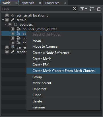
Creating Mesh Clusters from Mesh Clutters#
If you require more freedom in adjusting an existing Mesh Clutter, you can convert it to a mesh cluster using the relevant context-menu option.