Character Controller
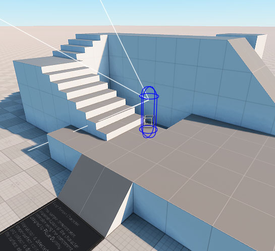
The Character Controller sample of the C# Component Samples demo demonstrates the following:
- Implementation of the first-person character controller using the First Person Controller component assigned to PlayerDummy
- Setting the collision capsule
- Detecting intersection via shape-surface collision and detailing collision via the surface intersection
First Person Controller Component#
The FirstPersonController component implements basic first-person player controls. The Player itself consists of a camera and a capsule shape to detect collisions. The component has the following settings available for adjustment:
- Input
- Gamepad Input
- Body parameters required for movements
- Camera parameters
- Movement parameters
- Auto Stepping for walking through obstacles with a certain height and slope
- Objects Interaction for simple interaction with physical objects
- Advanced Settings
- Debug settings to facilitate debugging
Creating a Player#
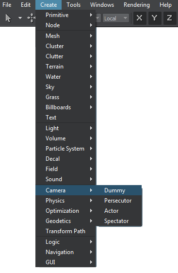
To create a player, you need to create a new Player Dummy (Create -> Camera -> Dummy) and add it to the scene.
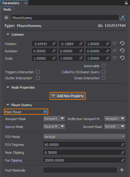
Enable the Main Player option for this Player in the Parameters window. Then add the FirstPersonController component to this node.
If you save the world and run the application, you can control a player with the standard settings.
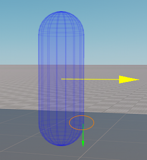
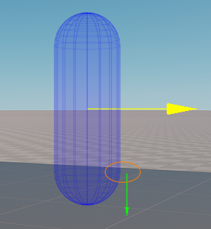
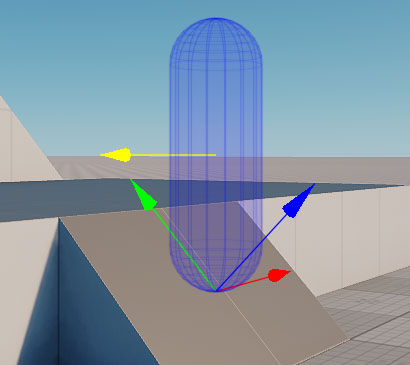
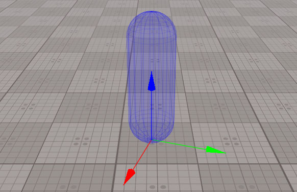
The player is represented by a capsule with the pivot located at the bottom of the capsule. When the player is created, the transformation is corrected based on the Y axis direction of the player. The Z axis is always directed upwards.
If the camera is assigned from the editor, its position and direction are based on the player's position and rotation in the world: the horizontal angle is the player's rotation angle along the Z axis, and the vertical angle is the actual camera's angle.
Settings#
The FirstPersonController component contains the following groups of settings that are displayed in the Node tab of the Parameters window after assigning the component to a node.
Input Settings#
The Input group allows setting keys to control the character using the keyboard and mouse: moving forward and backward, left and right, run, jump, and crouch modes. To assign the keys, Input.KEY enums are used. You can also adjust the mouse sensitivity that affects the camera rotation speed.
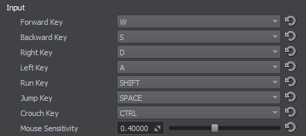
Input from the keyboard/mouse and gamepad are processed simultaneously. The action with a higher deviation has a priority.
Gamepad Input Settings#
The Gamepad Input group allows setting the gamepad control. Current settings are simplified: one stick can be set for horizontal movement, and the other for the camera rotation. Deadzone deviation is set for both sticks, and camera sensitivity can be set additionally. Any other actions can be set using Input.GAMEPAD_BUTTON keys.
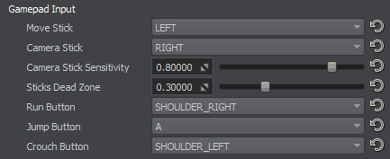
Input from the keyboard/mouse and gamepad are processed simultaneously. The action with a higher deviation has a priority.
Body Settings#
The Body group contains settings to adjust the player's physical body and shape defined by a capsule.

| Use Object Body | If enabled, the body and shape of the object this component is assigned to are used.
Notice
To enable this option, the object should have the Dummy Body and at least one Capsule shape. If either body or shape is missing, they will be created automatically based on the values set in the parameters below with the corresponding warning in the console. |
|---|---|
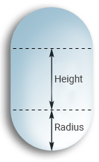
| Capsule Radius | The radius of the capsule that defines the player's shape. |
| Capsule Height | The height of the capsule that defines the player's shape. Keep in mind that this value defines only the height of the cylindrical part. The full height of the capsule is calculated as capsule height + 2 * capsule radius.
|
| Physics Intersection Mask | The mask that is used for selective detection of physics intersections (with other physical objects having bodies and collider shapes, or ray intersections with the collider geometry). |
| Collison Mask | The mask that is used to detect collisions of the shape with other physical objects. |
| Exclusion Mask | The mask that is used to prevent collisions of the shape with other physical objects. |
Camera Settings#
The Camera group contains settings to adjust the camera.

| Camera Mode | The mode of assigning the camera to the player:
|
|---|---|
| FOV | The camera's field of view, in degrees. |
| Near Clipping | Distance to the near clipping plane of the player's viewing frustum, in units. |
| Far Clipping | Distance to the far clipping plane of the player's viewing frustum, in units. |
| Camera Position Offset | Distance from the camera to the player's position. |
| Min Vertical Angle | The minimum vertical angle of the camera, i.e. maximum possible angle to look up. |
| Max Vertical Angle | The maximum vertical angle of the camera, i.e. maximum possible angle to look down. |
Movement Settings#
The Movement group contains all settings required for the character movements.
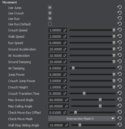
| Use Jump | The flag that enables jumping and all relevant parameters in the player logic. | ||||
|---|---|---|---|---|---|
| Use Crouch | The flag that enables crouching and all relevant parameters in the player logic.
Notice
If the player is crouching, and the Crouch button is released, it will raise only if there are no obstacles above. If the player raises, and there is an obstacle above or the Crouch button is pressed again, the player takes the crouch state again. |
||||
| Use Run | The flag that enables running and all relevant parameters in the player logic. | ||||
| Use Run Default | The flag that sets running as a default state of the player's movement. If this state is enabled, the walk state is enabled by using the Run Key. | ||||
| Crouch Speed | Horizontal speed used for crouching. | ||||
| Walk Speed | Horizontal speed used for walking. | ||||
| Run Speed | Horizontal speed used for running. | ||||
| Ground Acceleration | Horizontal acceleration applied when the player is on the ground. | ||||
| Air Acceleration | Horizontal acceleration applied when the player is in the air. | ||||
| Ground Damping | Damping of the horizontal speed when the player is on the ground. | ||||
| Air Damping | Damping of the horizontal speed when the player is in the air. | ||||
| Jump Power | Jump power of the player in the Run, Walk and Idle modes. | ||||
| Crouch Jump Power | Jump power of the player in the Crouch mode. | ||||
| Crouch Height | Height of the camera when the player is crouching. The minimum value equals to capsule radius x 2, the maximum height is equal to the capsule height. | ||||
| Crouch Transition Time | Time required for transition between the crouching and standing states. | ||||
| Max Ground Angle | Angle up to which the ground is considered to be even. If the angle is exceeded, the character can't stand still and slides down the slope. If the character climbs up the hill and its angle is more than this value, the character wouldn't climb up. | ||||
| Max Ceiling Angle | The value that defines the maximum angle at which the surface is considered to be the ceiling. If the surface the top part of the capsule contacts with has an angle that is less than this value, the character is considered to have hit the ceiling: its vertical speed becomes equal to 0 and the character starts to fall down. If the surface above the character has an angle that exceeds this value, the character slides along this surface. | ||||
| Check Move Ray Offset | Offset of the ray that checks the surface it would potentially move to. The minimum value is 0, the maximum is 0.1 unit.
|
||||
| Check Move Mask | Mask used to sort out intersections with the surface. | ||||
| Wall Stop Sliding Angle | Horizontal angle between the direction ray and contact point of the capsule with the wall. If the angle is less than this value, the player doesn't slide along the wall.
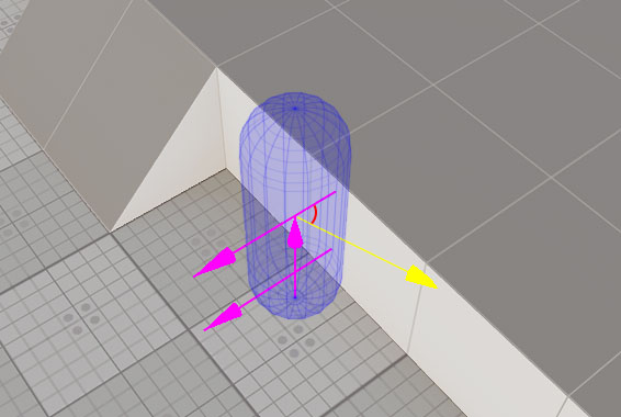
|
Auto Stepping Settings#
The Auto Stepping group of settings fine-tunes automatic climbing upon obstacles up to a certain height. The Auto Stepping process consists of three phases: raising the player to the obstacle height, moving it onto the obstacle and solving collisions, and dropping down on the surface of this obstacle and solving collisions.
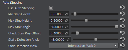
| Use Auto Stepping | The flag to toggle the Auto Stepping option. |
|---|---|
| Min Step Height | Minimum height of an obstacle for Auto Stepping to be applied. This is required to avoid applying Auto Stepping on even surfaces. |
| Max Step Height | Maximum height of an obstacle that can be climbed upon with Auto Stepping. |
| Max Stair Angle | Maximum slope angle for Auto Stepping to be applied. If the character steps on a surface with a slope, the angle of which is greater than the Max Stair Angle value, this last step is canceled. |
| Check Stair Ray Offset | Offset of the ray that checks the level of the potential stair for Auto Stepping. This offset is vertical and in the direction of the potential movement. |
| Stairs Detection Angle | Horizontal angle that defines the area for checking the contacts of the capsule with other objects in the movement direction. Allows avoiding false Auto Stepping near walls. |
| Stair Detection Mask | The mask for checking intersections with the stairs for Auto Stepping. If you have stairs with a complex geometry and want to simplify it for the Auto Stepping process, disable this mask for the complex geometry and enable for the simplified model. |
Objects Interaction Settings#
The Objects Interaction group contains settings that regulate simple physical interaction of the player with other physical objects.

| Use Objects Interaction | The flag to toggle interaction with other physical objects. These are the objects that have the Rigid Body assigned. |
|---|---|
| Impulse Multiplier | Multiplier for the impulse applied to the Rigid Body the player collides with. |
Advanced Settings#
The Advanced Settings group contains auxiliary settings for the player update.

| Player Fps | Minimum update framerate for the player. If the current FPS is less than this value, the player is updated several times per frame. |
|---|---|
| Collision Iterations | Number of iterations for resolving collisions. |
| Contacts Buffer Size | Maximum number of contacts processed for a collision. |
| Heavy Contacts Count | Maximum number of contacts up to which the Collision Iterations value is applied at processing contacts. If the number of contacts exceeds this value, then only one iteration is used to avoid performance drop. |
Debug Settings#
The Debug Settings group contains settings for debugging information. To see the debug info, the project should be run with the Debug configuration set.
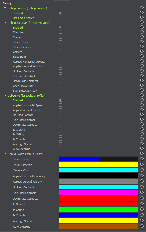
| Debug Camera | Enabling the Debug Camera creates a third-person camera that observes the player. This camera is controlled using the cursor arrows and + and - for changing the distance to the player. Enabling Use Fixed Angles positions this camera behind the player and makes it view the player's direction. |
|---|---|
| Debug Visualizer | Enabling the Debug Visualizer displays the selected debug information:
|
| Debug Profiler | Enabling the Debug Profiler displays the selected debug information in the Profiler:
|
| Debug Colors | Color pickers for setting the colors to be used for displaying the information in the Visualizer and Profiler. |
Accessing Demo Source Code#
You can study and modify the source code of this demo to create your own projects. To access the source code do the following:
- Find the C# Component Samples demo in the Demos section and click Install (if you haven't installed it yet).
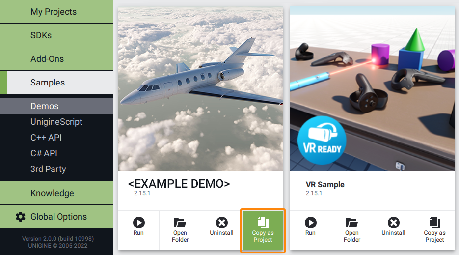
- After successful installation the demo will appear in the Installed section, and you can click Copy as Project to create a project based on this demo.
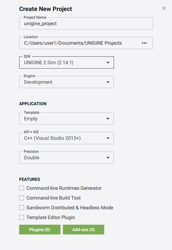
- In the Create New Project window, that opens, enter the name for your new project in the corresponding field and click Create New Project.
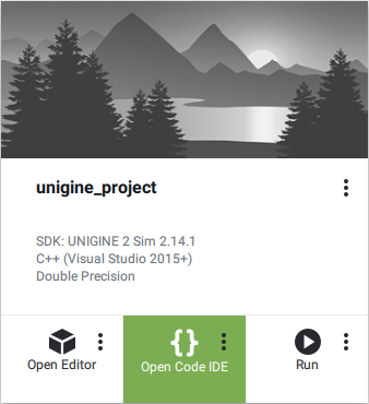
- Now you can click Open Code IDE to check and modify source code in your default IDE, or click Open Editor to open the project in the UnigineEditor.
The information on this page is valid for UNIGINE 2.19 SDK.
