相机矩阵
In UNIGINE, a camera has 2 matrices: the view and projection ones. They are used in rendering of the image from the camera to the viewport.在 UNIGINE 中,相机有 2 个矩阵:view 和 projection。它们用于将图像从相机渲染到视口.
Before getting to the main aspects of the camera matrices, it is necessary to know peculiarities of the coordinate system used by UNIGINE and refresh general knowledge of vector spaces and transformation matrices used for vertex rendering.在进入相机矩阵的主要方面之前,有必要了解 UNIGINE 使用的坐标系的特性,并刷新用于顶点渲染的向量空间和变换矩阵的一般知识。
Coordinate System坐标系#
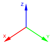
The 3D space in UNIGINE is represented by the right-handed Cartesian coordinate system: X and Y axes form a horizontal plane, Z axis points up.UNIGINE 中的 3D 空间由右手笛卡尔坐标系表示:X 和 Y 轴形成一个水平面,Z 轴指向上方。
Axes and Directions轴和方向#
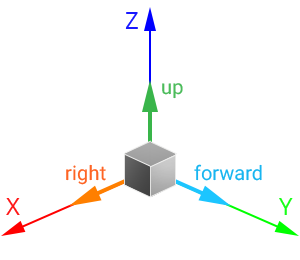
For nodes in the virtual scene:对于虚拟场景中的节点:
- The +Z axis is considered the upward direction. To move the node up/down, translate it along the Z axis.+Z 轴被认为是向上的方向。要向上/向下移动节点,翻译它沿着 Z 轴。
- The +Y axis is considered the forward direction. To move the node forward/backward, translate it along the Y axis.+Y 轴被认为是向前的方向。要向前/向后移动节点,翻译它沿着 Y 轴。
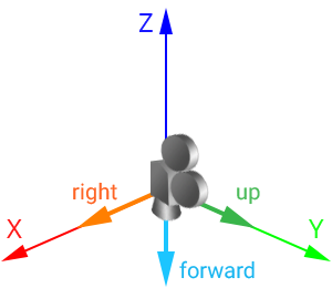
For the virtual camera: 对于虚拟相机:
- The +Y axis is considered the upward direction.+Y 轴被认为是向上的方向。
- The -Z axis is considered the forward direction.-Z 轴被认为是向前的方向。
A camera with a default identity transformation matrix looks down:带有默认恒等变换矩阵的相机向下看:
Working with Directions使用路线#
As you can see, direction vectors of nodes and cameras differ. For example, if you need to get the forward direction of the node, you should call the getAxisY() method for its transformation matrix:如您所见,节点和相机的方向向量不同。例如,如果需要获取节点的前向方向,则应为其变换矩阵调用 getAxisY() 方法:
// get the node transformation matrix
Mat4 t = node->getWorldTransform();
// get the node "forward" vector from the matrix
vec3 node_forward = t.getAxisY();
And if you need to get forward direction of the camera, you should call the -getAxisZ() method for its transformation matrix:如果您需要获得相机的前进方向,您应该为其变换矩阵调用 -getAxisZ() 方法:
// get the inverse modelview matrix as it is equal to the world transformation one
mat4 camera_transform = camera->getIModelview();
// get the camera "forward" vector from the matrix
vec3 camera_forward = -camera_transform.getAxisZ(); // the negative Z vector will be returned
However, the camera can be set to a player node. In this case, if you simply call getAxisY() as for any other node, you will get the upward direction of the camera. To avoid this, implement the following:但是,相机可以设置为玩家节点.在这种情况下,如果您像任何其他节点一样简单地调用 getAxisY(),您将获得相机的向上方向。为避免这种情况,请执行以下操作:
// get the node transformation matrix
Mat4 t = node->getWorldTransform();
// get the "forward" vector from the matrix
vec3 forward = vec3(node->isPlayer() ? -t.getAxisZ() : t.getAxisY());
Forward direction of the node/camera (if set to the player node) can also be obtained by using the Node::getDirection()/getWorldDirection() method:节点/相机的前进方向(如果设置为播放器节点)也可以使用Node::getDirection()/getWorldDirection()方法获得:
vec3 forward = node->getDirection(node->isPlayer() ? Math::AXIS_NZ : Math::AXIS_Y);Vector Spaces and Transformation Matrices向量空间和变换矩阵#
There are the following vector spaces:有以下向量空间:
- Local space is a space in which all vertices of an object are defined relative to the center of this object.Local space 是一个空间,其中一个对象的所有顶点都是相对于该对象的中心定义的。
- World space is a space in which all vertices of an object are defined relative to the center of the world.World space 是一个空间,其中对象的所有顶点都是相对于世界中心定义的。
- View space is a space in which all vertices of an object are defined relative to the camera.View space 是一个空间,其中对象的所有顶点都是相对于相机定义的。
- Clip space is a space in which all vertices of an object are defined in a cuboid of [-1;1] dimensions for every axis. The Z coordinate of the vertex specifies how far away the vertex is from the screen.Clip space 是一个空间,其中对象的所有顶点都定义在每个轴的 [-1;1] 维度的长方体中。顶点的 Z 坐标指定了顶点离屏幕的距离。
- Screen space is a space in which all vertices of an object are flattened and have screen coordinates.Screen space 是一个空间,其中对象的所有顶点都被展平并具有屏幕坐标。
When rendering a vertex, it is transformed from one space into another in the following order:渲染顶点时,它按以下顺序从一个空间转换到另一个空间:

The matrices used to transform between spaces are the following:用于在空间之间进行变换的矩阵如下:
-
World Transformation Matrix stores transformation of the object relative to the world origin. This matrix is used to transform the the object's vertices from the local space to the world space: the matrix is multiplied by each vertex of the object.世界变换矩阵存储对象相对于世界原点的变换。该矩阵用于将对象的顶点从局部空间转换到世界空间:矩阵乘以对象的每个顶点。
In UNIGINE, such transformation is performed automatically when the node is added into the world. When a node is added into the world as a child of another node, it has also a Local Transformation Matrix that stores transformation of the object relative to its parent. To transform the local transformation matrix of such an object to the world one, the object's local transformation matrix is multiplied by the local transformation matrix of the parent. To get more information about local and world transformation matrices, check the Matrix Hierarchy chapter.在 UNIGINE 中,当节点被添加到世界中时,这种转换会自动执行。当一个节点作为另一个节点的子节点添加到世界中时,它还有一个本地变换矩阵,用于存储对象相对于其父节点的变换。为了将这样一个对象的局部变换矩阵变换到世界一,对象的局部变换矩阵乘以父对象的局部变换矩阵。要获得有关局部和世界变换矩阵的更多信息,请查看矩阵层次结构章节。
-
View Matrix is used to transform the object's vertices from the world space to the view space.查看矩阵用于将对象的顶点从世界空间转换到视图空间。
注意In UNIGINE, the view matrix is called modelview.在 UNIGINE 中,视图矩阵称为 modelview。 - Projection Matrix is used to transform the object's vertices from the view space to the clip space.投影矩阵用于将对象的顶点从视图空间转换到裁剪空间。
Each node added into the world has the world transformation matrix. However, passing this matrix to a shader for vertex rendering is unreasonable: it will lead to precision loss because of double to float coordinates conversion. For this reason, in UNIGINE, the node is transformed to the view space first: the product of the world transformation matrix and the view matrix is calculated on CPU and passed to the shader. Such matrix is called Modelview (in its generic meaning). 每个加入世界的节点都有世界变换矩阵。但是,将此矩阵传递给着色器进行顶点渲染是不合理的:由于双浮点坐标转换会导致精度损失。为此,在 UNIGINE 中,节点首先转换到视图空间:世界转换矩阵和视图矩阵的乘积在 CPU 上计算并传递给着色器。这样的矩阵称为 Modelview(按其一般含义)。
Thus, transformation of coordinates of an object's vertex can be represented by the following formula:因此,对象顶点坐标的变换可以用以下公式表示:
VertexClip = ProjectionMatrix * ModelviewMatrix * VertexLocalHere the ModelviewMatrix is the product of the world transformation matrix and the view matrix. The order of matrix multiplication is read from right to left.这里的 ModelviewMatrix 是世界变换矩阵和视图矩阵的乘积。矩阵乘法的顺序是从右到左读取的。
View Matrix查看矩阵#
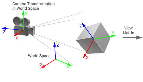
In UNIGINE, the View matrix is the 4x4 matrix that controls the way the camera looks at the scene. The view matrix is equal to the inverse camera world transformation matrix: it stores position and rotation of the camera in world space.在 UNIGINE 中,View 矩阵是4x4 矩阵,用于控制相机查看场景的方式。这查看矩阵等于逆相机世界变换矩阵:它存储相机在世界空间中的位置和旋转。
The matrix is used to transform vertices of the object from the world space to the view space (coordinates of vertices are set relative to the camera origin): the camera's view matrix is multiplied by the object's world transformation matrix and then the resulting matrix is multiplied by the object's vertices.矩阵用于将对象的顶点从世界空间转换到视图空间(顶点坐标相对于相机原点设置):相机的视图矩阵乘以对象的世界变换矩阵,然后乘以得到的矩阵通过对象的顶点。
 |
 |
Object and camera in world space世界空间中的物体和相机 |
Object in view space视图空间中的对象 |
Projection Matrix投影矩阵#
The Projection matrix is a matrix that defines how vertices are rendered on the screen. The values of the projection matrix depend on the type of projection:投影矩阵是一个矩阵,用于定义顶点在屏幕上的呈现方式。投影矩阵的值取决于投影类型:
-
For the orthographic projection, the following matrix is used:为了正投影,使用以下矩阵:

-
For the perspective projection, the following matrix is used:为了透视投影,使用以下矩阵:

By default, the projection matrix of the camera doesn't store an aspect ratio of the screen (width to height): aspect correction is performed automatically for the current viewport. If manual aspect correction is done, the automatic aspect correction for the viewport must be disabled to avoid incorrect results.默认情况下,相机的投影矩阵不存储屏幕的纵横比(宽度到高度):自动为当前视口执行纵横比校正。如果进行了手动纵横比校正,则自动纵横比校正必须禁用视口以避免错误结果。
If you change FOV (or width and height for orthographic projection), near and far clipping planes, the matrix is updated.如果更改 FOV(或正交投影的宽度和高度)、近剪裁平面和远剪裁平面,矩阵将更新。
The projection matrix is used to transform vertices of the object from the view space to the clip space. This space is represented by a cuboid with [-1;1] dimensions for every axis and used for clipping vertices: all vertices inside this volume will be rendered on the screen. In this space, the Z coordinate of each vertex specifies how far away a vertex is from the screen.投影矩阵用于将对象的顶点从 view space 转换为 clip space。该空间由每个轴的尺寸为 [-1;1] 的长方体表示,用于裁剪顶点:该体积内的所有顶点都将在屏幕上呈现。在这个空间中,每个顶点的 Z 坐标指定了一个顶点离屏幕的距离。
Then the vertex coordinates in the clip space are automatically transformed to normalized device coordinates by using perspective division. Mapping these coordinates to the screen space is performed on GPU by using the viewport transform vector that stores the following:然后使用透视分割将裁剪空间中的顶点坐标自动转换为归一化的设备坐标。将这些坐标映射到屏幕空间是通过使用存储以下内容的视口变换向量在 GPU 上执行的:
(width, height, 1/width, 1/height)Camera Matrices Simulator相机矩阵模拟器#
Take a look at the following spreadsheet to get a full picture of how camera matrices are handled in UNIGINE. It shows the way the World Transformation, View, and Projection matrices affect the coordinates of a vertex which can be used for debug purposes.查看以下电子表格以全面了解 UNIGINE 中相机矩阵的处理方式。它显示了世界变换、视图和投影矩阵影响可用于调试目的的顶点坐标的方式。
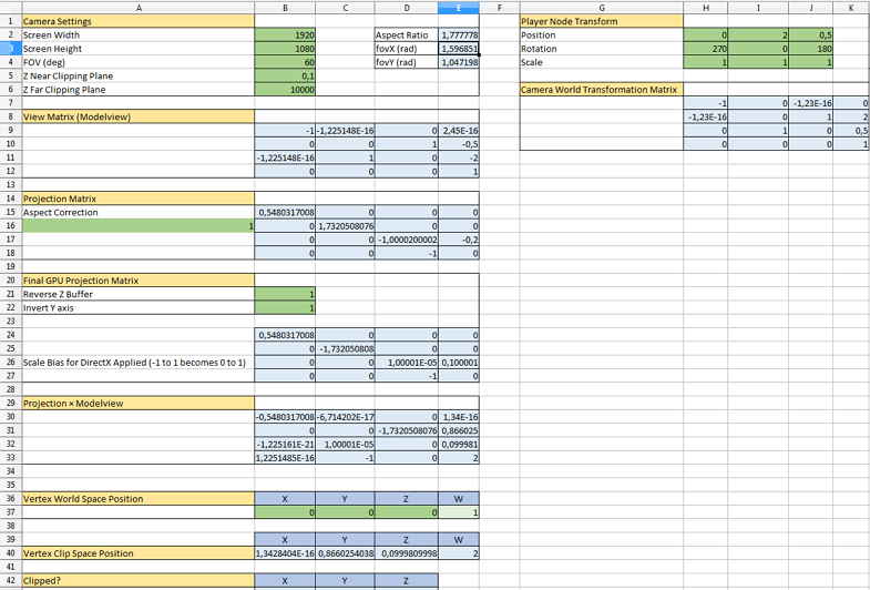
Download the UNIGINE camera matrices simulator.xlsx下载 UNIGINE 相机矩阵模拟器.xlsx
本页面上的信息适用于 UNIGINE 2.18.1 SDK.
