Light Sources Parameters
This article contains parameters common for the omni-directional light source, projected light source, environment probes, voxel probes, and world light source. Each light source has unique parameters, described in the corresponding articles. Note that not all the parameters, described in this article, are available for each light source.
Shadow settings described in this article are common for the omni-directional and projected light sources. Shadow settings for the world light source are described in the corresponding article.
Light Settings
| Light Mask | Shadow mask controls rendering of a shadow cast by an object lit by a light source. | ||||
|---|---|---|---|---|---|
| Viewport Mask | Viewport mask. For the light to be rendered, its viewport mask must match the player's viewport mask. | ||||
| Color Mode | Color calculation mode for the light source. The following mode are available:
|
||||
| Color | Color of the light in the RGBA format. By default, the light is white.
|
||||
| Color Filter | Color multiplier for the light source color (calculated using the color temperature value). This can be used to imitate colored glass. The parameter is available only when the Temperature color mode is set. | ||||
| Temperature | Light source temperature used for light color calculation. The maximum value is 40000.
|
||||
| Intensity | Multiplier for the light color used to control color intensity. The higher the value, the brighter the light is.
|
||||
| Lux | Intensity of the light color (as perceived by the human eye) in lux. In UNIGINE, all light sources have the intensity of 1 by default, which is equal to 100000 lux. | ||||
| Mode | Light's mode that defines its contribution in the light baking process.
|


Attenuation Settings
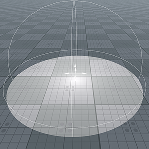
| Power | Light attenuation power used to simulate light intensity gradual fading. This parameter determines how fast the intensity decreases up to the attenuation distance set for the light source.
|
||||||
|---|---|---|---|---|---|---|---|
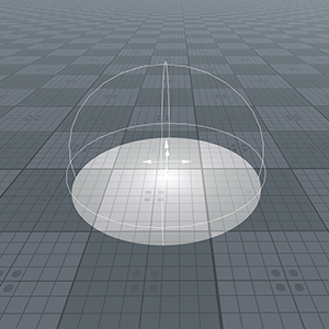
| Distance | Distance from the light source shape, at which the light source doesn't illuminate anything. In other words, this parameter determines the size of the area illuminated by the light source.
|
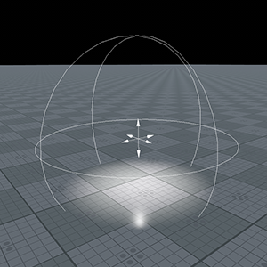
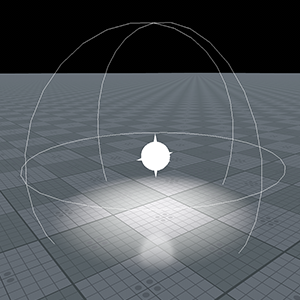
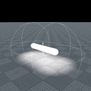
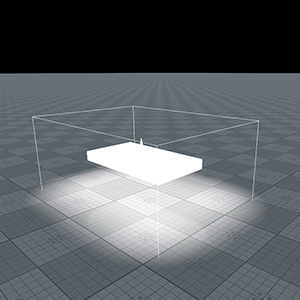
Shape Settings
Distance Visibility Settings
| Light | Distance at which the light source starts fading. If the distance is set to inf, the source is always rendered. |
|---|---|
| Shadow | Distance up to which the casted shadows completely fade out. |
| Fade | Distance at which the light gradually disappears. This parameter enables to render the light with decreasing radiance after the Light distance is past. |
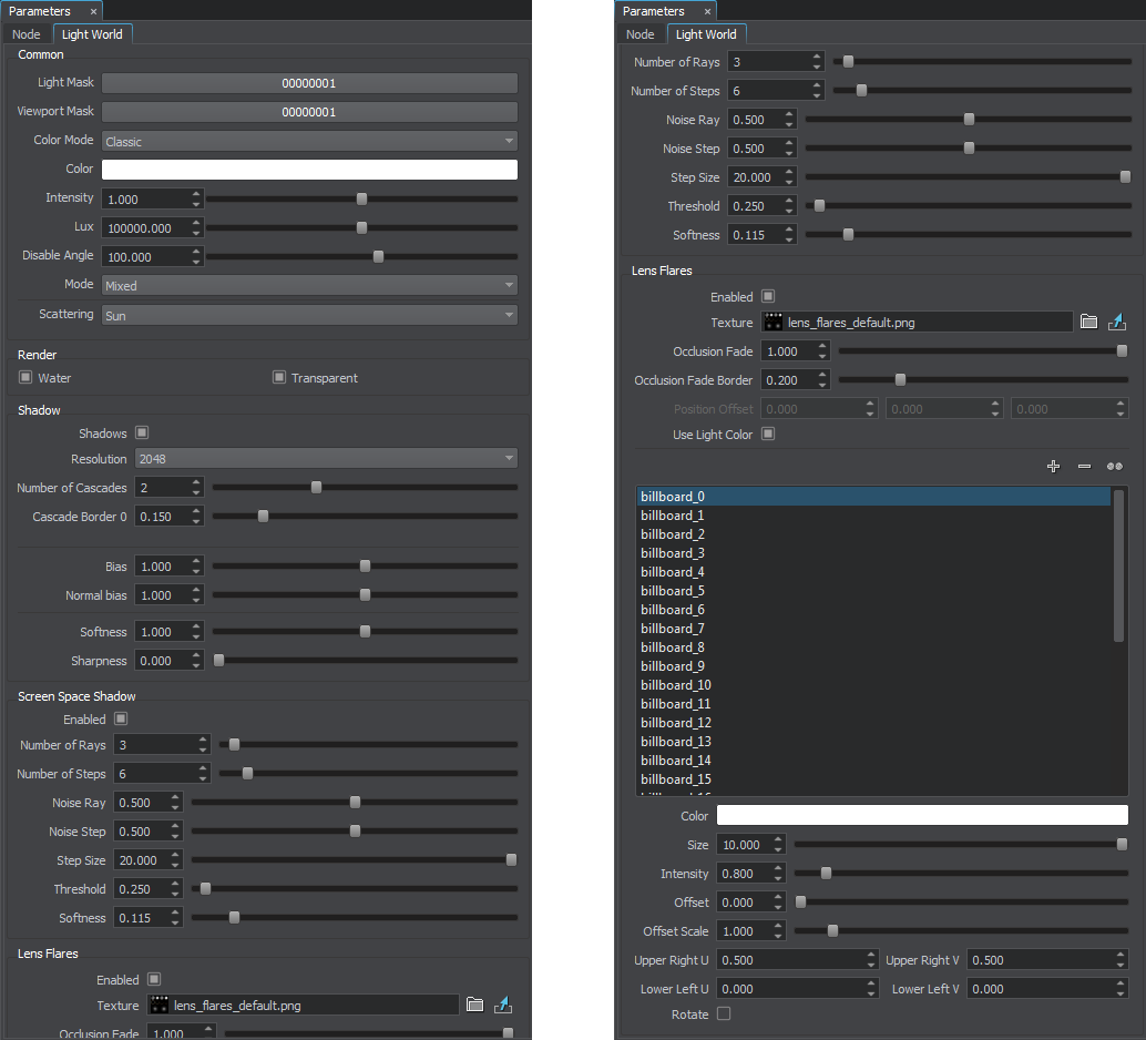
Rendering Settings
Shadow Settings
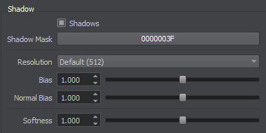
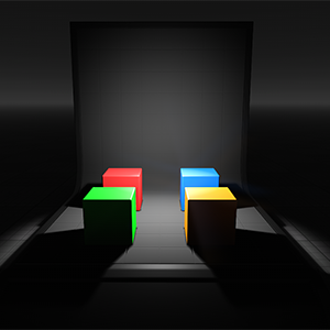
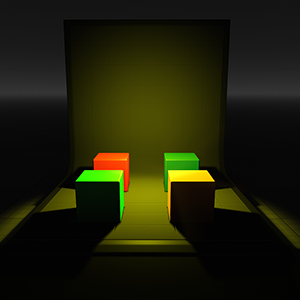
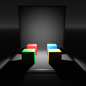
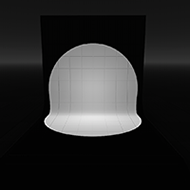
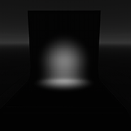
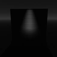
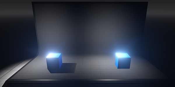
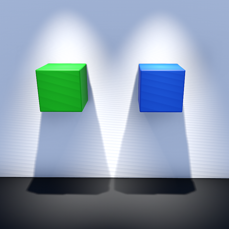
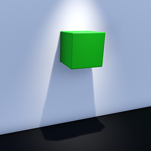
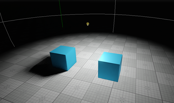
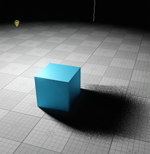
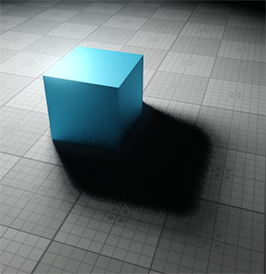
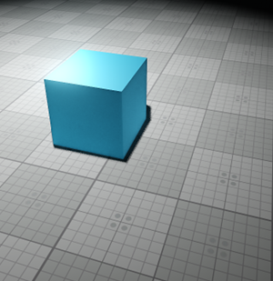
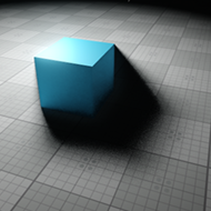
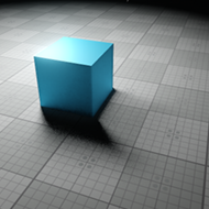
| Shadows | Enables or disables shadows from the light source.
Shadows from omni light on (the left cube) and off (the right cube)
|
||||||||
|---|---|---|---|---|---|---|---|---|---|
| Resolution | Size of the shadow map that defines shadow quality.
|
||||||||
| Bias | Shadow bias that is used to correct inexact shadowing of the scene objects. It controls the depth offset added to the current depth value stored in the shadow map. Such offset is adaptively calculated with respect to the slope angle of the light source, its resolution and also the distance to the light source at shadow map applying
|
||||||||
| Normal bias | Shadow bias that is achieved by shifting the surface on which the shadow falls. The surface is shifted along normals stored in the normal map.
|
||||||||
| Softness | Size of the blur applied to the shadow edge.
|


Screen Space Shadow Settings
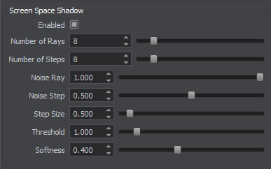
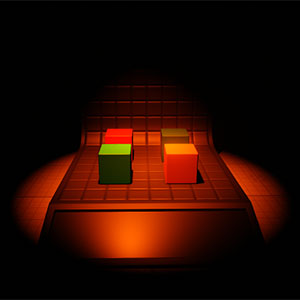
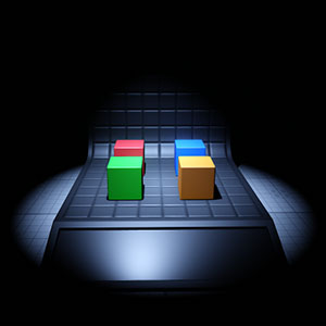
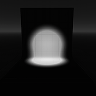
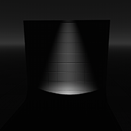
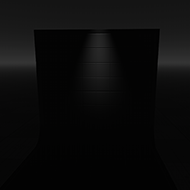
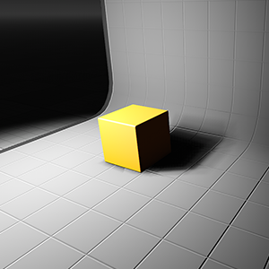
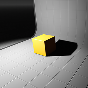
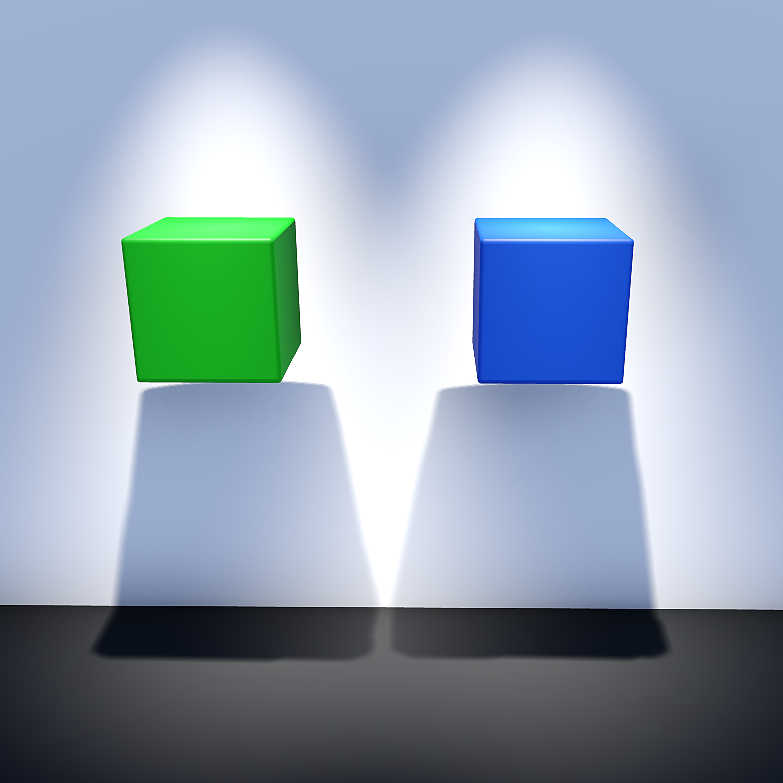
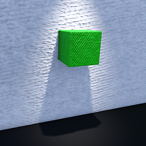
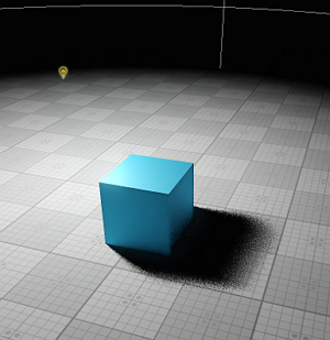
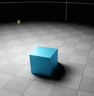
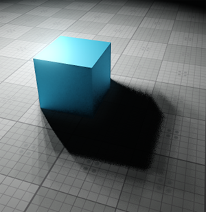
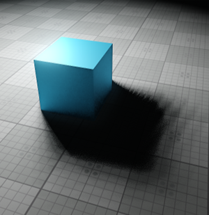
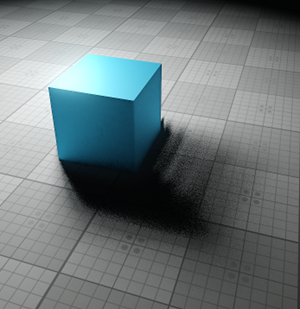
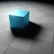
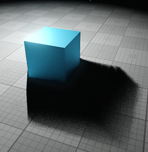
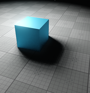
| Enabled | Enables or disables screen space shadows from the light source.
Screen Space Shadows from omni light on (the left cube) and off (the right cube). Shadows are disabled.
|
||||||||
|---|---|---|---|---|---|---|---|---|---|
| Number of Rays | Number of rays used in screen space ray tracing. The higher the number of rays, the more the computation of pixel shading is accurate.
|
||||||||
| Number of Steps | Number of steps each ray traces. The higher the number of steps, the more the computation of pixel shading is accurate.
|
||||||||
| Noise Ray |
Ray tracing dispersion. The higher the noise, the more the direction of rays is chaotic.
|
||||||||
| Noise Step | Dispersion of steps. The higher the noise, the more the steps are scattering.
|
||||||||
| Step Size | Length of each step used in ray traced shadows.
|
||||||||
| Threshold | Limit of samples passing the screen space shadowing.
|
||||||||
| Softness | Size of the blur applied to the shadow edge.
|

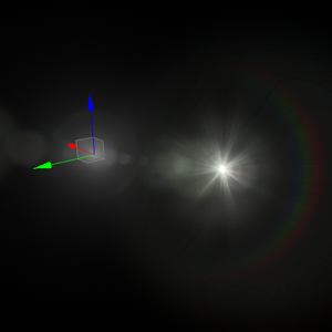
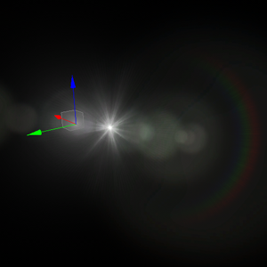
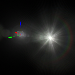
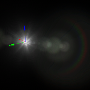
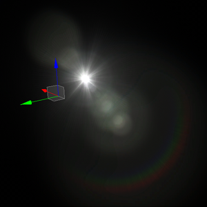
Lens Flares Settings
Lens Flares simulate the effect of lights refracting inside camera lens. They are used to represent very bright lights or to add more atmosphere to your scene. The settings described below are used per-light, you can also use the lens flares camera effect, which is applied to all lights and bright objects (e.g. having an emissive material with high intensity assigned).
Lens Flares are rendered as billboards, each associated with a part of a single texture and having a set of parameters, that determine its appearance and behavior. So, you can customize and fine tune your lens flares to fit your needs.
| Enabled | Enables or disables lens flares from the light source. By default this effect is disabled. Notice The maximum number of lights on the scene for which the per-light flares will be rendered is 32. |
||||
|---|---|---|---|---|---|
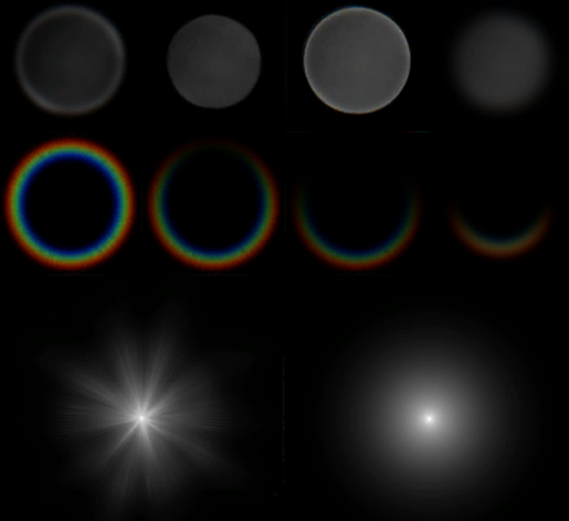
| Texture |
A texture used to render billboards representing lens flares. The default texture is shown in the image below. For each billboard you can specify UV coordinates within this texture to determine its appearance. You can set your own texture, that contains the appearance for all the billboards to be used.
|
||||
| Occlusion Fade | Lens flare occlusion fade value for the cases when the light source becomes occluded by an object. By the value of 0.0f, lens flares disappear abruptly, as the light source becomes occluded by an object. If 1.0f is set, lens flares will fade out gradually. Notice Transparent objects are currently treated as opaque ones (i.e. they won't occlude flares). |
||||
| Occlusion Fade Border | Lens flare occlusion fade value for the cases when the light source becomes occluded by the edges of the screen. By the value of 0.0f, lens flares disappear abruptly, as the light source becomes occluded by the edges of the screen. If 1.0f is set, lens flares will fade out gradually. | ||||
| Position Offset | An offset of the center of lens flares from the world position of the light source. Notice
This parameter is not available for World Lights
|
||||
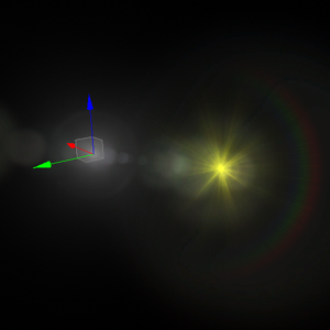
| Use Light Color | When enabled, the lens flares will have the same color as the light source. |
Lens Flares Billboards Settings
Each flare is represented by a separate billboard, The default number of billboards is 30, but you can change it if necessary by adding, removing, or cloning selected billboards in the list via the corresponding buttons.
As you select a billboard in the list, its parameters become available for editing in the fields below.
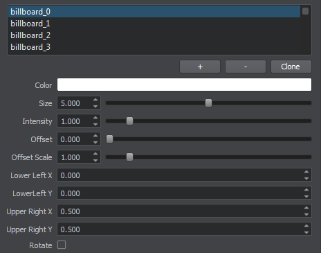
| Color | Color multiplier for the selected billboard. Texture colors will be multiplied by this value. By default the color is white.
|
||||
|---|---|---|---|---|---|
| Size | This parameter controls the size of the selected billboard.
|
||||
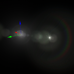
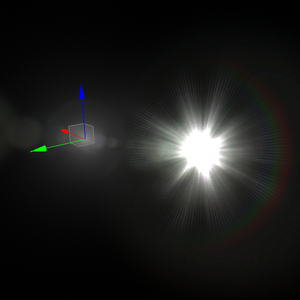
| Intensity | Multiplier for the billboard color used to control color intensity. The higher the value, the brighter the billboard is.
|
||||
| Offset | Offset determines the distance between the light source and the billboard along the vector oriented from the light source to the screen center. The lower the absolute value is, the closer to the light source the billboard will be. Negative values indicate that the distance is measured in the opposite direction.
|
||||
| Offset Scale | Determines how the billboard changes its scale depending on the distance from the light source. As the offset from the light source increases:
|
||||
| Lower Left X | X-coordinate of the lower left corner of the selected billboard in the lens flares texture, in the range [0.0, 1.0], e.g., the value equal to 0.5 corresponds to the middle of the texture. | ||||
| Lower Left Y | Y-coordinate of the lower left corner of the selected billboard in the lens flares texture, in the range [0.0, 1.0], e.g., the value equal to 0.5 corresponds to the middle of the texture. | ||||
| Upper Right X | X-coordinate of the upper right corner of the selected billboard in the lens flares texture, in the range [0.0, 1.0], e.g., the value equal to 0.5 corresponds to the middle of the texture. | ||||
| Upper Right Y | Y-coordinate of the upper right corner of the selected billboard in the lens flares texture, in the range [0.0, 1.0], e.g., the value equal to 0.5 corresponds to the middle of the texture. | ||||
| Rotate | Enables or disables rotation of the lens flare billboard. When enabled the top of the billboard will always face the center of the screen. |