Visual Representation
Visual representation of nodes can be changed by adjusting parameters of its surfaces on the Node tab of the Parameters window.
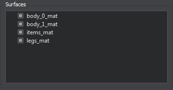
To change the surface parameters, select the required surface in the hierarchy and tweak its parameters. For each surface, the parameters listed below are available for editing.
Rendering Parameters
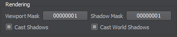
This section provides parameters for setting up rendering of the surface and its shadows.
| Viewport Mask | Viewport mask of the surface. |
|---|---|
| Shadow Mask | Shadow mask of the surface. |
| Cast Shadows | Flag indicating if the surface casts shadows from non-world lights (omni, projected, and environment probe light sources). |
| Cast World Shadows | Flag indicating if the surface casts shadows from world lights. |
LOD Parameters
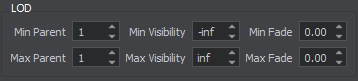
This section provides parameters for setting up surface LODs.
| Min Parent | Reference object, from which the minimum visibility distance of the surface is measured.
|
|---|---|
| Max Parent | Reference object, from which the maximum visibility distance of the surface is measured. The same principle as for the minimum parent is used to count it. The reference object is used to ensure simultaneous LOD switching for all surfaces. |
| Min Visibility | Minimum visibility distance from the camera when a surface starts to appear on the screen. By default it is -inf. |
| Max Visibility | Maximum visibility distance when a surface is no longer fully visible: it can either disappear completely or start to fade out. By default it is inf. |
| Min Fade | Minimum fade distance, over which the surface fades in until it is completely visible. Along this distance the engine will automatically interpolate the level of detail from alpha of 0.0 (completely invisible) to 1.0 (completely visible). Fading in starts when the camera has reached the minimum distance of surface visibility and is in the full visibility range. |
| Max Fade | Maximum fade distance, over which the surface fades out until it is completely invisible. Fading out starts when the camera has reached the maximum distance of surface visibility and is out of the full visibility range. |
Material Parameters
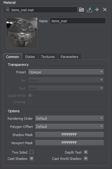
In this section, a material can be assigned to the surface and then material's parameters can be tweaked (if the material is editable). Here you can also inherit a new material from the material assigned to the surface: it will be assigned automatically. To inherit the material, click  right to the field with the material name.
To set the default material, click
right to the field with the material name.
To set the default material, click  right to the field with the material name.
The material parameters can also be changed on the Material tab of the Parameters window: it becomes available when the target material is selected in the Material Hierarchy window.