Matrix Transformations
A lot of calculations in Unigine are performed by using matrices. Actually, matrix transformations are one of the main concepts of 3D engines. This article contains an explanation of matrix transformations with usage examples.
See Also#
- An article about mat4 and dmat4 Unigine data types.
- The description of Math Matrix Functions.
Transformations#
In simple terms, a matrix in 3D graphics is an array of numbers arranged in rows and columns:

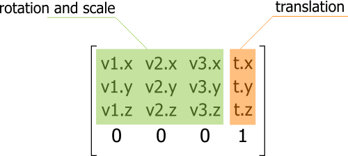
Usually, 4x4 matrices are used. Such size (4x4) of matrices is caused by the translation state in 3D space. When you put a new node into the world, it has a 4x4 world transform matrix that defines the position of the node in the world.
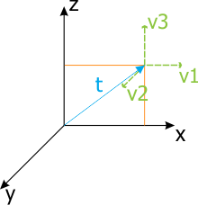
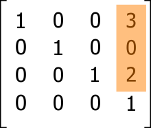
In Unigine, matrices are column major (column-oriented). Hence, the first column of the transform matrix represent the X vector v1, the second represent Y vector v2, the third represent Z vector v3, and the fourth represent the translation vector t. First three columns show directions of axes and the scale of the origin. The last column contains the translation of the local origin relatively to the world origin.
Identity Matrix#
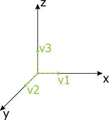
The world origin has the following matrix:

This matrix is called identity matrix, a matrix with ones on the main diagonal, and zeros elsewhere. If a matrix is multiplied by the identity matrix, that won't change anything: the resulting matrix will be the same as it was before multiplying.
If the local origin has the identity matrix, it means the local origin and the world origin are coincident.
Rotation#
To change the orientation of the local origin, the first three columns of the matrix should be changed.
To rotate the origin along different axes, you should use proper matrices:

In the matrices given above, α is a rotation angle along the axis.
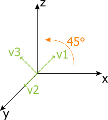
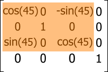
The next matrix shows the rotation of the local origin along the Y axis at 45 degrees:
|
|
Translation#
The last column of the transform matrix shows the position of the local origin in the world relatively to the world origin. The next matrix shows the translation of the origin. The translation vector t is (3, 0, 2).
|
|
Scaling#
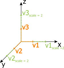
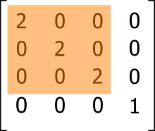
The length of the vector shows the scale coefficient along the axis.
To calculate the vector length (also known as magnitude), you should find a square root of the sum of the squares of vector components. The formula is the following:
|vector length| = √(x² + y² + z²)The following matrix scales the local origin up to 2 units along all axes.
|
|
Cumulating Transformations#
The order of matrix transformations in code is very important.
If you want to implement a sequence of cumulating transformations, the transformations order in code should be as follows:
TransformedVector = TransformationMatrixN * ... * TransformationMatrix2 * TransformationMatrix1 * VectorTransformations are applied one by one starting from TransformationMatrix1 and ending with TransformationMatrixN.
Example#
This example shows the difference between two orders of matrix transformations.
The code example below gets the material ball object. In the first case, rotation is followed by translation and in the second case, translation is followed by rotation.
In the AppWorldLogic.h file, define the material_ball node smart pointer.
// AppWorldLogic.h

/* ... */

class AppWorldLogic : public Unigine::WorldLogic {

public:
	/* .. */
private:
	Unigine::NodePtr material_ball;
};
In the AppWorldLogic.cpp file, perform the following:
- Include the UnigineEditor.h, UnigineVisualizer.h, UnigineConsole.h headers.
- Use using namespace Unigine and using namespace Unigine::Math directives: names of the Unigine and Unigine::Math namespaces will be injected into global namespace.
- Enable the visualizer by passing show_visualizer 1 command to the run() function of the Console class.
- Get the material ball from the Editor.
- Create new rotation and translation matrices.
- Calculate new transformation matrix and apply it to the material ball.
- Render the world origin by using renderVector() method of the Visualizer class.
// AppWorldLogic.cpp file
#include "AppWorldLogic.h"
#include "UnigineWorld.h"
#include "UnigineVisualizer.h"
#include "UnigineConsole.h"

// inject Unigine and Unigine::Math namespaces names to global namespace
using namespace Unigine;
using namespace Unigine::Math;

/* ... */

int AppWorldLogic::init() {

	// enable the visualizer for world origin rendering
	Console::run("show_visualizer 1");

	// get the material ball
	material_ball = World::getNodeByName("material_ball");

	// create rotation and translation matrices
	Mat4 rotation_matrix = (Mat4)rotateZ(-90.0f);
	Mat4 translation_matrix = (Mat4)translate(vec3(0.0f, 3.0f, 0.0f));

	// create a new transformation matrix for the material ball
	// by multiplying the current matrix by rotation and translation matrices
	Mat4 transform = translation_matrix * rotation_matrix * material_ball->getTransform();

	// set the transformation matrix to the material ball
	material_ball->setTransform(transform);

	return 1;
}

int AppWorldLogic::update() {
	// render world origin
	Visualizer::renderVector(Vec3(0.0f,0.0f,0.1f), Vec3(1.0f,0.0f,0.1f), vec4(1.0f,0.0f,0.0f,1.0f));
	Visualizer::renderVector(Vec3(0.0f,0.0f,0.1f), Vec3(0.0f,1.0f,0.1f), vec4(0.0f,1.0f,0.0f,1.0f));
	Visualizer::renderVector(Vec3(0.0f,0.0f,0.1f), Vec3(0.0f,0.0f,1.1f), vec4(0.0f,0.0f,1.0f,1.0f));

	return 1;
}
To change the order, just change the line of cumulating transformations:
Mat4 transform = rotation_matrix * translation_matrix * material_ball->getTransform();The result will be different. The pictures below show the difference (camera is located at the same place).
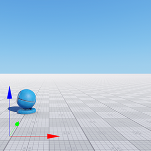
|
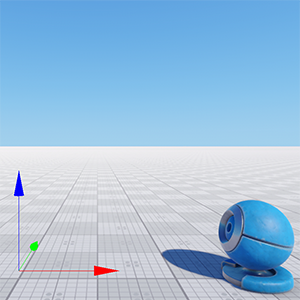
|
|
Order: rotation and translation
|
Order: translation and rotation
|
The pictures above show the position of the meshes related to the world origin.
Matrix Hierarchy#
One more important concept is the matrix hierarchy. When a node is added into the world as a child of another node, it has a transformation matrix that is related to the parent node. That is why the Node class distinguishes between the functions getTransform(), setTransform() and getWorldTransform(), setWorldTransform(), which return the local and the world transformation matrices respectively.
What is the reason of using a matrix hierarchy? To move a node relative to another node. And when you move a parent node, child nodes will also be moved.
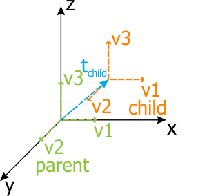
|
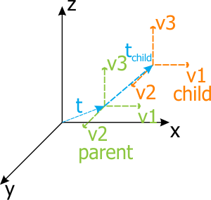
|
|
Parent origin is the same with the world origin
|
Parent origin has been moved and the child origin has also been moved
|
Pictures above show the main point of the matrix hierarchy. When the parent origin (node) is moved, the chlld origin will also be moved and the local transformation matrix of the child would not be changed. But the world transformation matrix of the child will be changed. If you need the world transformation matrix of the child related to the world origin, you should use the getWorldTransform(), setWorldTransform() functions; in case, when you need the local transformation matrix of the child related to the parent, you should use the getTransform(), setTransform() functions.
Example#
The following example shows how important the matrix hierarchy is.
In this example, we get the node and clone it. Then we change transformation matrices of these nodes. We review two cases:
- The two nodes are independent.
- One node is the child of the other.
In the AppWorldLogic.h file, define smart pointers of the material_ball child and parent nodes.
// AppWorldLogic.h

/* ... */

class AppWorldLogic : public Unigine::WorldLogic {

public:
	/* .. */
private:
	Unigine::NodePtr material_ball_child;
	Unigine::NodePtr material_ball_parent;
};
In the AppWorldLogic.cpp, implement the following code:
// AppWorldLogic.cpp
#include "AppWorldLogic.h"
#include "UnigineEditor.h"
#include "UnigineVisualizer.h"
#include "UnigineConsole.h"
#include "UnigineLog.h"

using namespace Unigine;
using namespace Unigine::Math;

int AppWorldLogic::init() {

	// enable the visualizer for world origin rendering
	Console::run("show_visualizer 1");

	// get the material ball and clone it
	material_ball_child = World::getNodeByName("material_ball");
	material_ball_parent = material_ball_child->clone();

	// make the one node the child of another
	material_ball_parent->addChild(material_ball_child);

	// create rotation and translation matrices for the first material_ball
	Mat4 rotation_matrix = (Mat4)rotateZ(-90.0f);
	Mat4 translation_matrix = (Mat4)translate(vec3(3.0f, 0.0f, 0.0f));

	// create translation matrix for the second (parent) material ball
	Mat4 translation_matrix_clone = (Mat4)translate(vec3(0.5f, 0.0f, 1.0f));

	// create new transformation matrices for the material balls
	Mat4 transform = translation_matrix * rotation_matrix * material_ball_child->getTransform();
	Mat4 transform_clone = translation_matrix_clone * material_ball_parent->getTransform();

	// set the transformation matrices to the material balls
	material_ball_child->setTransform(transform);
	material_ball_parent->setTransform(transform_clone);


	return 1;
}

int AppWorldLogic::update() {
	// render world origin
	Visualizer::renderVector(Vec3(0.0f,0.0f,0.1f), Vec3(1.0f,0.0f,0.1f), vec4(1.0f,0.0f,0.0f,1.0f));
	Visualizer::renderVector(Vec3(0.0f,0.0f,0.1f), Vec3(0.0f,1.0f,0.1f), vec4(0.0f,1.0f,0.0f,1.0f));
	Visualizer::renderVector(Vec3(0.0f,0.0f,0.1f), Vec3(0.0f,0.0f,1.1f), vec4(0.0f,0.0f,1.0f,1.0f));

	return 1;
}

int AppWorldLogic::shutdown() {
	// clear smart pointers
	material_ball_child.clear();
	material_ball_parent.clear();

	return 1;
}
If you comment the following line:
// make the one node the child of another
material_ball_parent->addChild(material_ball_child);
you get a different result:
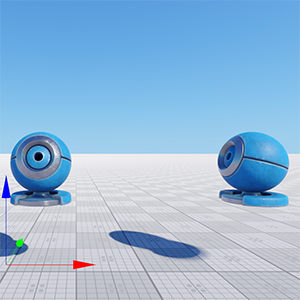
|
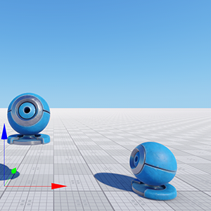
|
|
Parent-child nodes
|
Nodes are independent
|
When nodes are independent, they have different local and world transformation matrices. In case of parent-child nodes, the child's local transformation matrix remains the same after moving, but the world transformation matrix is changed (you can check that by using the debug profiler).