Getting Started
This article covers UNIGINE-specific terminology and concepts and is highly recommended for all new users.
How Are Virtual Worlds Organized?
Project
When you create an application on UNIGINE, it is represented by a project. A project is a "container" for the application code, content, and meta-data.
A project can consist of one or several complex 3D scenes, which are called worlds.
All projects are managed via the UNIGINE SDK browser.
World
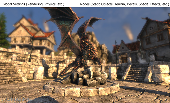
A UNIGINE-based virtual world is a 3D scene that contains a set of different scene graph nodes (e.g. static meshes, lights, cameras, etc.) placed into specified positions, and global settings (rendering, physics, etc.) applied to the whole scene.
A scene graph in UNIGINE is a multi-root tree (hierarchy) of nodes.
Each world is represented by the XML file with the .world extension.
Node
In terms of UNIGINE, all objects added to the scene are called nodes. Nodes can be of different types, determining their visual representation and behavior.
There is a rich set of built-in node types. Though the set covers almost all of required cases, it can be manually extended by the user.
Every node has a transformation matrix, which encodes position, rotation, and scale of the node in the world.
There are node types which appear visually: Objects, Decals, and Effects. All of them have surfaces to represent their geometry (mesh). Other node types (Light Sources, Players, etc.) are invisible.
Node parameters are regularly stored in the .world file, but also can be saved into a separate XML file with the .node extension (and later be referenced from the .world file via the special nodes called Node References).
Mesh
A mesh is a collection of polygons defining the object's geometry. It has the following properties:
- Each mesh has one or several surfaces.
- A maximal number of polygons per surface is 2147483647 (ObjectMeshStatic, ObjectMeshSkinned) or 65535 (ObjectMeshDynamic).
- There are 2 UV channels for texturing.
- Mesh supports vertex colors.
An animation in UNIGINE can be performed by skinned meshes (bone-based), morph targets (keyframe) or dynamic meshes (code-controlled).
In the runtime, meshes are stored in proprietrary UNIGINE formats with .mesh (static mesh + optional animation data) and .anim (external animation data) extensions.
When importing an FBX model to the engine, it is automatically converted to the .mesh format. Meshes can also be imported directly via the UNIGINE plugins built-in to 3ds Max or Maya.
Surface
A surface is a named non-overlapping subset of the object geometry (i.e. object mesh). Each surface can have its own material or property assigned. It is also possible to enable/disable surfaces independently from each other.
Surfaces can be organized in a hierarchy within a mesh (it can be used for LOD switching).
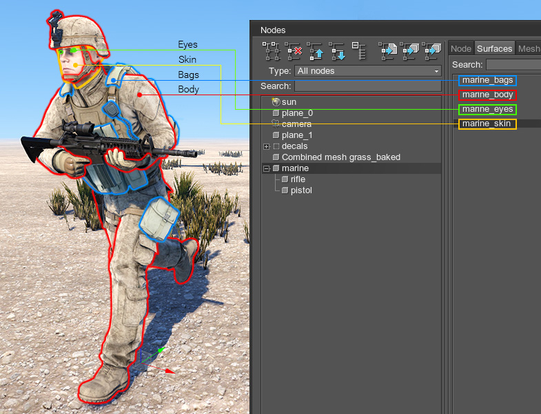
At the picture below, a soldier 3D mesh consist of 4 surfaces: eyes, skin, bags (body armor, radio set, bag), and body (overalls, shoes, hard hat, gloves).
Material
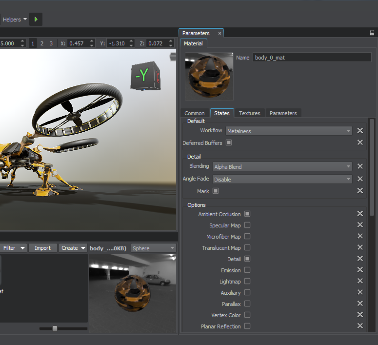
In terms of UNIGINE, a material is a rule defining how the surface will look like: its interaction with lights, reflection parameters, etc. It is based on:
- Vertex, fragment and geometry shaders that actually draw the material based on different conditions.
- User-defined textures passed to shaders.
- States that specify conditions, basing on which the appropriate shaders will be applied.
- Parameters defining how shaders will be used.
UNIGINE provides a rich set of built-in base materials out of the box. The recommended way is to inherit a new user material from a base one and tweak it. You can also create custom shaders either using UUSL (Unified UNIGINE Shader Language) or HLSL/GLSL, but in the latter case you would need to migrate your custom shaders with every SDK release by yourself.
Besides regular materials applied to the certain surfaces, there is a special type of materials called post materials, that are applied above the final screen composition.
Material Hierarchy
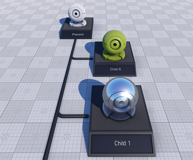
Materials are organized in hierarchy with parameters inheritance and overloading (much like in object-oriented programming). When a material is inherited, all its parameters are inherited from the parent. If a parameter value is changed for the parent, it will be automatically changed for the child as well, unless it was overridden (set to a different value) for the child before that.
Example: a material A has two parameters (color: blue and specular power of 1.4), a material B is inherited from the material A and has color parameter overridden (red). If we change specular power to 2.0 in the material A, then the material B will have the following parameters: red color (overridden) and 2.0 value of specular power (inherited).
By using parameter inheritance it is very convenient to mass control values of multiple materials parameters.
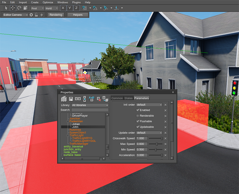
Property
How Do We See the Virtual World?
For visual representation, UNIGINE uses a standard perspective projection. The orthogonal projection is also available.
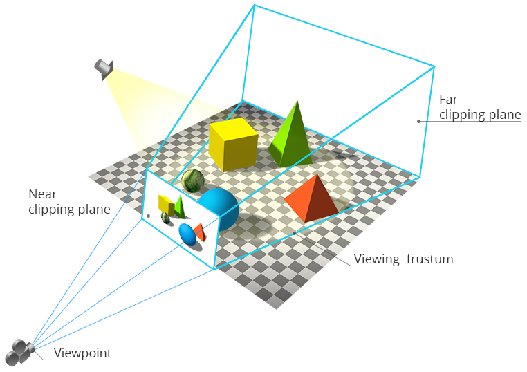
In UNIGINE, the way how the world is seen is based on the 3 entities:
- A camera is a structure containing 2 matrices: modelview and projection. Through this structure, you set the camera parameters: field of view, masks, near and far clipping planes, and post materials. Then, the camera is passed to a Viewport that will render an image from this camera. The camera is also set to the Player that will further control its position.
- A viewport receives a camera and renders an image from it on the screen. In addition, it provides all functions of the main renderer, for example, cube maps rendering, stereo rendering, panoramic rendering and so on.
- A player is a node controlled through the input devices (keyboard, mouse, joystick). It has the camera set to it. Once a player has changed its position, its internal camera's modelview matrix will be changed as well.
UNIGINE features several types of players: Player Dummy, Player Actor, Player Persecutor and Player Spectator.
Rendering
UNIGINE has a combination of full deferred renderer with forward rendering techniques:
- All opaque (non-transparent) geometry is rendered in the deferred pass.
- Transparent geometry is rendered in the forward pass.
To know more about the applied rendering techniques, see the Rendering Sequence article.
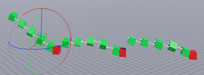
LODs
Smooth alpha-blended levels of details (LODs) are used to decrease geometry complexity of 3D objects, when these objects move away from the camera, making it possible to lighten the load on the renderer.
Usually, LODs are used for:
- Switching the high-polygonal surfaces of the mesh to the low-polygonal ones.
- Switching the surfaces with complex materials to the surfaces with the simplified optimized materials.
- Switching several high-polygonal surfaces to a single simplified surface.
- Switching one node type to the other (for example, switching the high-polygonal mesh to the billboard, a two-polygonal object that always faces the camera)
Switching between LODs can depend not only on the distance from the camera, but also from the distance from the certain object.
UNIGINE offers two mechanisms of LODs switching:
- Disable one LOD and enable another at the specified distance defined by two values: maximum visibility distance of the first LOD (Max Visibility) and minimum visibility distance of the second LOD (Min Visibility).
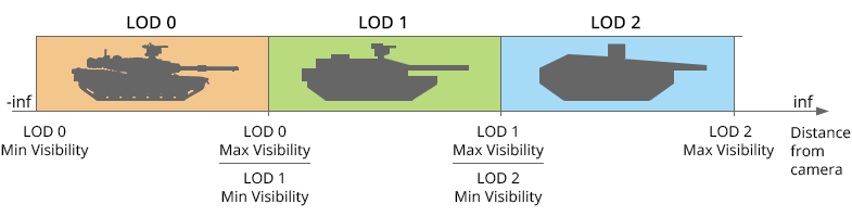
- Smoothly fade one LOD into another at the specified interval defined by two values: minimum fade distance of the first LOD (Min Fade) and maximum fade distance of the first LOD/minimum fade distance of the second LOD (Max Fade).

See the Setting up object LODs tutorial for the details.
Bit Masking
Bit masking defines whether two entities affect each other or not. It can be used to:
- Render some objects to the viewport and not to render the others.
- Apply collision to some bodies and not to apply to the others.
- Render shadows for some objects and not to render for the others.
- Apply physics interaction for some objects and ignore the others.
A bit masking algorithm compares 32-bits masks of each of two nodes using binary operator and. If masks match, one object will influence another object; if they don't, the objects won't interact.
How Is Physical Behaviour Defined?
UNIGINE features a built-in simplified game-like Newton physics. The use cases of using physics properties rather than hard-coding objects animation are the following:
- Collision detection (preventing moving through walls).
- Simulating perfectly elastic collisions (redistribution of kinetic energy).
- Simulation of simple mechanisms by rigid bodies and destructable joints.
- Simulation of basic physical phenomena: gravity, friction, buoyancy.
- Procedural destruction of meshes.
- Simulation of cloth and ropes movement.
Physics is simulated with its own update FPS and is in effect within the physics simulation distance. Physical properties can be applied to the objects only.
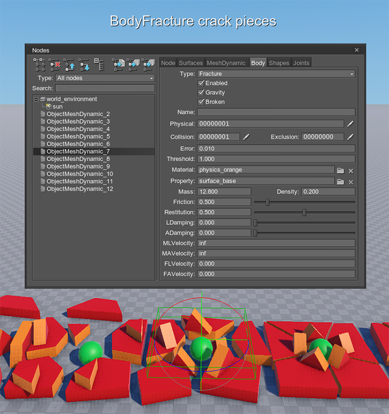
Body
To assign an object some physical properties so that it could participate in interactions between objects or external physical forces, it should have a body. There are several types of bodies: Rigid, Rag Doll, Fracture, Rope, Cloth, Water, Path.
Almost like in the real worlds, virtual physics of the body follows concepts of velocity, force, mass, density an so on.
Shape
While a body simulates various types of physical behavior, a shape represents the volume (sphere, capsule, cylinder, box, convex hull) that a rigid body occupies in space. A physically simulated object usually has one body and one or several shapes which allow objects to collide with each other.
Collision Detection
A collision detection algorithm detects contact points between shapes and prevents them from penetrating each other. Contact points and normals are accessible via API.
Joint
Joints are used to connect several objects with respect to the mass balance. There are different types of joints: Fixed, Hinge, Ball, Prismatic, Cylindrical, Suspension.
Global Physics Settings
There are global physics settings (gravity, penetration factor, etc.) affecting all physical objects present in the world.
How to Add Content to the Virtual World?
There are two methods of source file importing from a third-party software into the UNIGINE-friendly runtime format (e.g. .node, .mesh, .terrain, etc.):
- Importing into a runtime format with saving into an intermediate format with UnigineEditor ( .fbx, .tga, .lcp, etc.).
- Importing directly into a runtime format with built-in to 3ds Max or Maya plugins.
UnigineEditor
UnigineEditor allows you to assemble a virtual world: import and set nodes, assign materials and properties to them, setup lighting, set the global settings (physics, rendering, etc.) and more. It features What You See Is What You Get approach: you can instantly see the scene with final quality (as in the runtime).
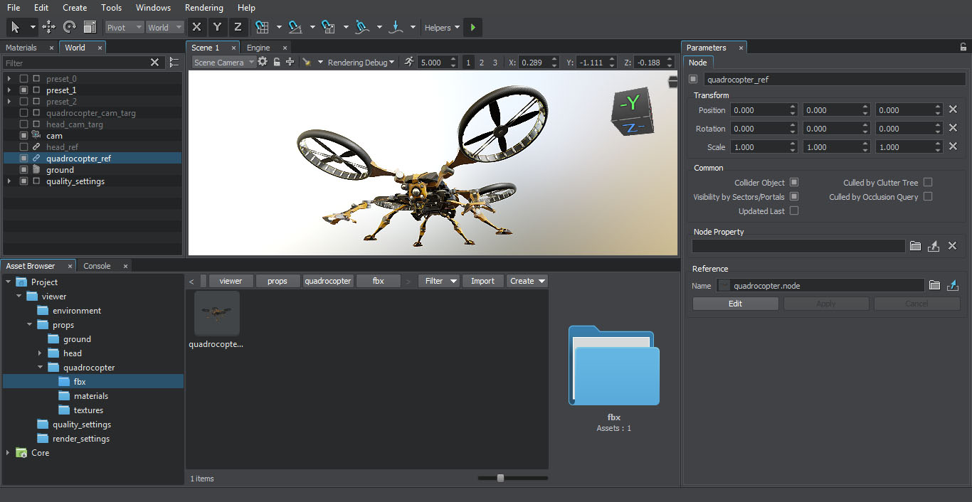
Watch the tutorial below to know how to import an FBX file to UNIGINE:
How to Control the Virtual World?
Programming Languages
To create your own project with UNIGINE, you can use the following programming languages:
- C++ for maximum performance and seamless integration with the existing code base.
- C# for a good balance between speed and ease of use.
- UnigineScript, fast iterative scripting language featuring instant compilation and thousands of useful functions.
All the APIs are unified: every class, method, and constant are accessible through any API. However, there are minor language-specific differences.
To know more, see the following usage examples articles:
- UnigineScript API, C++ API and C# API usage examples
- Examples of UnigineScript extension using C++ API
- Examples of UnigineScript extension using C# API
Mixing Languages
By design, UNIGINE allows having different programming languages (C++, C# and UnigineScript) for different pieces of your project. Usually, C++ is used for base classes and performance consuming operations; UnigineScript is used for application logic. You can call methods from one API when using another, and manually expand API functionality. Alternatively, you can stick to a single language, e.g. write your application in pure C++.
Runtime Logic
UNIGINE has three main logic components:
-
System Logic is the code that is run during the whole application life cycle (its scope exists even when switching worlds).
- For applications written using UnigineScript, the system logic is written to the system script file (unigine.cpp).
- For C++ or C# applications, AppSystemLogic.cpp is created in the source folder of your project. It has implemented methods to put your logic code inside.
-
World Logic is the logic of the virtual world. The logic takes effect only when the world is loaded.
- For applications written using UnigineScript, the world logic is written to the world script file (*.cpp named after your project).
- For C++ or C# applications, AppWorldLogic.cpp is created in the source folder of your project. It has implemented methods to put your logic code inside.
-
Editor Logic is the logic of the editor. The logic takes effect only when the editor is loaded.
- For C++ or C# applications, AppEditorLogic.cpp is created in the source folder of your project. It has implemented methods to put your logic code inside.
It is highly recommended to see the execution sequence to know the details, including multi-threaded mode.
Intersection Detection
UNIGINE features a fast intersection detection algorithm. It can be used for ray casting, calculating line-of-sight (LOS), calculating height above terrain (HOT), etc.
Intersections are found between the node's bounding volume and another bounding volume of the specified size.
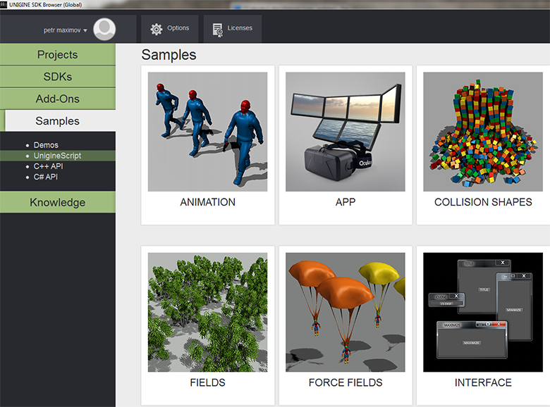
Samples and Demos
UNIGINE provides a rich set of built-in samples and demo projects covering basic principles of working with the engine (operations with the built-in nodes, output rendering, GUI setting, etc.). There are different samples for each of 3 programming languages. All samples come with the full source code. To check them, go to SDK browser -> Samples tab.
Now you are prepared to start your experience with UNIGINE. Enjoy!