Unigine.JointSuspension Class
| Inherits from: | Joint |
Warning
This joint type is deprecated and will be removed in the upcoming releases. It is recommended to use the Wheel Joint instead.
This class is used to create a suspension joint. The bodies that represent both a frame and a wheel must be rigid bodies.
Example#
The following code illustrates connection of two rigid bodies (frame and wheel) using a suspension joint.
Source code (C#)
JointSuspension joint = new JointSuspension(frame, wheel);
// setting joint anchor coordinates
joint.WorldAnchor = wheel.Object.WorldTransform * new dvec3(0.0f);
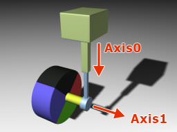
// setting joint axes coordinates
joint.WorldAxis0 = new vec3(0.0f,0.0f,1.0f);
joint.WorldAxis1 = new vec3(0.0f,1.0f,0.0f);
// setting linear damping and spring rigidity
joint.LinearDamping = 2.0f;
joint.LinearSpring = 200.0f;
// setting lower and upper suspension ride limits [-0.5; 0.0]
joint.LinearLimitFrom = -0.5f;
joint.LinearLimitTo = 0.0f;
// setting target suspension height
joint.LinearDistance = 0.5f;
// setting maximum angular velocity and torque
joint.AngularVelocity = -20.0f;
joint.AngularTorque = 10.0f;
// setting common joint constraint parameters
joint.LinearRestitution = 0.2f;
joint.AngularRestitution = 0.2f;
joint.LinearSoftness = 0.2f;
joint.AngularSoftness = 0.2f;
// setting number of iterations
joint.NumIterations = 8;See Also#
- A set of UnigineScript API samples located in the <UnigineSDK>/data/samples/physics/ folder:
- car_00
- car_01
- car_03
JointSuspension Class
Properties
float CurrentLinearDistance#
The current suspension compression.
float CurrentAngularVelocity#
The current velocity of wheel rotation.
float AngularVelocity#
The target velocity of wheel rotation.
set
Sets a maximum velocity of wheel rotation.
set value -
Velocity in radians per second.
float AngularTorque#
The maximum torque of the attached angular motor.
set
Sets a maximum torque of the attached angular motor.
set value -
Maximum torque. If a negative value is provided, 0 will be used instead.
float AngularDamping#
The angular damping of the joint (wheel rotation damping).
set
Sets an angular damping of the joint (wheel rotation damping).
set value -
Angular damping. If a negative value is provided, 0 will be used instead.
float LinearSpring#
The rigidity coefficient of the suspension.
set
Sets a rigidity coefficient of the suspension.
set value -
Rigidity coefficient. If a negative value is provided, 0 will be used instead.
float LinearLimitTo#
The high limit of the suspension ride.
set
Sets a high limit of the suspension ride.
set value -
Limit in units.
float LinearLimitFrom#
The low limit of the suspension ride.
set
Sets a low limit of the suspension ride.
set value -
Limit in units.
float LinearDistance#
The target height of the suspension.
set
Sets a target height of the suspension.
set value -
Height in units.
float LinearDamping#
The linear damping of the suspension.
set
Sets a linear damping of the suspension.
set value -
Linear damping. If a negative value is provided, 0 will be used instead.
vec3 WorldAxis1#
The wheel spindle axis in the world coordinates.
set
Sets a wheel spindle axis in the world coordinates.
set value -
Wheel spindle axis in the world coordinates.
vec3 WorldAxis0#
The suspension axis in the world coordinates.
set
Sets suspension axis in the world coordinates.
set value -
Suspension axis in the world coordinates.
vec3 Axis11#
The wheel spindle in coordinates of the wheel (body 1).
set
Sets a wheel spindle axis in coordinates of the wheel (body 1): an axis around which a wheel rotates when steering.
set value -
Wheel spindle axis in coordinates of the wheel (body 1).
vec3 Axis10#
The wheel spindle axis in coordinates of the frame (body 0).
set
Sets a wheel spindle axis in coordinates of the frame (body 0): an axis around which a wheel rotates when moving forward (or backward).
set value -
Wheel spindle axis in coordinates of the frame (body 0).
vec3 Axis00#
Suspension axis coordinates.
set
Sets coordinates of suspension axis, along which a wheel moves vertically. This is a shock absorber.
set value -
Suspension axis.
Members
JointSuspension ( ) #
Constructor. Creates a suspension joint with an anchor at the origin of the world coordinates.JointSuspension ( Body body0, Body body1 ) #
Constructor. Creates a suspension joint connecting two given bodies. An anchor is placed between centers of mass of the bodies.Arguments
- Body body0 - Frame to be connected with the joint.
- Body body1 - Wheel to be connected with the joint.
JointSuspension ( Body body0, Body body1, vec3 anchor, vec3 axis0, vec3 axis1 ) #
Constructor. Creates a suspension joint connecting two given bodies with specified suspension and spindle axis coordinates and an anchor placed at specified coordinates.Arguments
Last update:
2021-04-29
Help improve this article
Was this article helpful?
(or select a word/phrase and press Ctrl+Enter)