Light Sources Parameters
Unigine light sources regarded in this section share similar parameters (except for prebaked lightmaps that cannot be tweaked dynamically). They can vary to some extend depending on the source specifics, but the general set is regarded below. For the unique parameters refer to the sources articles.
Deferred Lighting
Deferred lighting is a simplified and faster method to render lights. The main advantage of this method of calculations is that allows substantially much faster and less resource consuming rendering, though producing middle-quality results:
- By deferred lighting all the objects are uniformly rendered with default Phong shading. Materials setting contribute only to the diffuse and specular components. It must be noted, that being monochrome, specular component is not exactly precise, though remaining visually satisfactory.
- No additional effects like anisotropy or Fresnel reflection are possible.
- Anti-aliasing is also unavailable on surfaces lit by deferred lights.
Another variant of deferred lighting is deferred shading. It is super-simplified, even more faster, yet its quality is poorer.
Deferred Distance
Deferred distance parameter allows to introduce the principles of LOD system to lighting. When the camera moves away from the bounding sphere of the light source to the specified distance (and further), the lights will start to be rendered as deferred. This gives a very significant speed boost in the scenes with the large number of light sources.
Color
Most noticeable property of the light source is its color in RGBA format, determining both the plausibility of virtual representation and the aesthetic component. If the resulting color combinations are tepid and not accurate, the liveliness of the scene can suffer.
Multiplier
Multiplier provides fine control over color intensity of the emitted light.
- The minimum value of 1.0 corresponds to the least saturated light color.
- The maximum value of 100 equals the most bright and intense color.
Radius
The distance of light irradiation is limited to the sphere with specified radius (in units), allowing to adjust the exact area of the scene to be illuminated. Since dynamic lighting is quite a resource hungry task, the sources should be placed with sagacity and shrewdness to avoid lags by loading.
Attenuation
Attenuation allows to simulate the natural phenomenon of light intensity gradual fading. This parameter determines how fast the intensity diminishes up to the radius distance set for the source.
- Decreasing the value to the minimum of 0.001 will result in light sphere having sharp and clear edges, which usually contributes to an unnatural feeling about the final rendered image.
- Increasing the value up to the maximum of 1.0 will render softly dispersed light at the non-illuminated areas border.
Light Mask
Each light source can selectively influence the objects in the scene. If the illumination of some object creates an undesired effect, it can be simply omitted when rendering the light from the source. On the other hand, adding extra lights to a specific object without affecting the rest of the scene can be invigorating and effectively serve the artistic purposes.
To define the objects which would be illuminated by the light source, the matching bit mask should be set for both the source and the object. The bit mask is a string of bits representing the selected decimal numbers in binary system, that is used for sequential comparison with another mask. Two masks match if at least one bit in the masks matches.
Viewport Mask
This mask allows light to be rendered in the viewport. It means, all the objects (or those that are masked) will be rendered lit. For that, this mask should match the camera Viewport mask. (See the detailed info).
Diffuse Scale
The diffuse component of the light cast by a source represents a directional light illuminating an object. Coming from a single direction, that is defined by the source position in the virtual world, it is spread across the object facing surface. Diffuse scale controls the intensity of this light component. The material of the surface also has its own diffuse characteristic, which is multiplied by the source diffuse scale to get the final rendered image. The scale varies in range from 0 to 2.
Specular Scale
The next component simulating light interaction with surfaces is specular one. In contrast to diffuse reflection, where incoming light is reflected in a broad range of directions. It is responsible for creating highlights from incoming light on a surface and is a viewpoint-dependent characteristic. Specular scale modulates the reflective light intensity and is multiplied by the equivalent property specified for the material. The scale varies in range from 0 to 2.
Specular Power
The scattering range of the specular reflection can be fine-tuned using the specular power parameter. It controls the breadth of highlights on the illuminated objects and is multiplied by the glossiness set for the material, because the more polished its surface is, the sharper and more uniformly the light rays are reflected.
- The minim value of 0 represents more pointed specular highlights.
- the maximum value of 2 equals broad and more diffuse highlights.
Visible Distance
The created world can be of a substantial size, so as the camera moves away from the light source, it can pass out of the viewing frustum many units away. To lighten the computational load, it is reasonable to set the limits of its visibility. The first step is to define a distance, up to which the light will be rendered as intense as the the sources settings specify. If the distance is set to infinity, the source is always rendered.
Fade Distance
The second step of distant-dependent rendering optimization is to set a fade distance for the source. It enables to perceive the light source as gradually disappearing and to avoid visual artifact of flickering. The given parameter allows to render the light with decreasing radiance after the visible distance is past. When having gone beyond the fade distance, the source will not be rendered at all.
Shadow Distance
If the shadows are enabled for the light source, their disappearance should be as imperceptible to the eye as possible. Shadow distance provides such an opportunity. It defines the distance up to which the casted shadows will fade out to nonexistence slowly blending into the background.
Shadow Settings
Shadowing is undoubtedly an essential aspect of lighting model. But besides the general shadows technique implementation, the ability to tweak the shadow's look is also vital. The specifics of the shadows appearance help to achieve graphic realism by enhancing viewer's perception of the relative object positions in virtual world.
The shadows from the light source can be enabled or disabled by checking the appropriate box on the Shadow tab. The following parameters will define its appearance:
Shadow Offset
The shadows position can be cheated by setting the offset along the three coordinates relative to the source position. It can help to gain necessary visual effect of altering shadow shape without changing the light direction. To aid the offset orientation, there are shown additional visualizer axes, repeating the source's axes alignment.
Shadow Map Size
The size of the shadow map defines the shadow quality and influences the rendering speed. It can be flexibly adapted by choosing the appropriate The larger the map used for a source casting shadows is, the smoother and true to life the result is, though gained at the cost of higher memory consumption. The lower the resolution is, the more blocky and jagged the shadows outline appears. However, the low-resolution maps significantly alleviate memory loading, especially when several maps are used at the same time. Still, they are more processor-intensive while calculating the softness (?).
The following sizes of the shadow map are available for flexible adaptation to the particular requirements:
- 64
- 128
- 256
- 512 (set by default as balanced between the visual quality and performance limitations)
- 1024
- 2048
- 4096
Shadow Ambient Color
Effective simulation of the natural environment demands that the shadows should not simply be absolutely dark regions projecting object geometry, but include diffuse contribution of the light propagating in a scene and used to color the shadowed surface. The ambient color parameter allows to control the shadow density by specifying the intensity of the base ambient color (corresponding to the light source one) in the shadowed areas.
- The minimum value of 0 corresponds to the most dense shadow cast by the light source. However, the actual darkness of the shadow will depend on the amount of light in the scene.
- The minimum value of 1 results in having no visible shadows, as the ambient color intensity in shadowed and non-shadowed areas will be equal.
Shadow Bias
When testing if a point is shadowed from the light emitted by the source, its distance is compared to the depth value stored in the shadow map. Since the precision of depth map is limited, one map pixel may contain depth values for several sampled points along the lit surface. If the closest point is stored as a depth value, others will appear father away from light and will be rendered shadowed. This false positive test result is called a self-shadowing artifact.
However, occasional inexact shadowing of the scene objects can be corrected using the bias parameter. It controls the depth offset added to the current depth value stored in the shadow map.
- If the shadow appears to "bleed", the bias value should be increased. This procedure eliminates the self-shadowing effect, as the points will appear closer to light source when compared to the map depth value. On the other hand, if the bias value is set too high, the shadow will look detached from the object casting it.
- Decreasing the bias makes the depth test less inclusive, but results in banding and moire pattern on the surface.
Shadow Slope
The shadow artifacts are not only conditioned by the numerical in-precision of shadow map depth values. Geometry component should also be taken into consideration. A shadow map texel is projected to some surface area in the scene despite representing a single depth value. As a result, this area is shadowed as perpendicular to the light source, even if it slants away. But the offset on steep slopes needs to be quite bigger than on the flat ones, making it hard to choose one constant value appropriate for correct shadowing. The Slope parameter compensates for this fact and determines how much bias should be applied in compliance with the steepness of the slope (up to 90 degrees). Increasing the value will add to the applied offset The slope value is added to the constant bias value.
Shadow Softness
For the shadows to have a natural look, it is essential to gain the refine and smooth penumbra transitions along its outline. The Softness parameter defines the size of the blur applied to the shadow edge.
- Increasing softness parameter is very salutary for low-resolution shadow maps: you can get by with using them if high softness values are applied. However, pixel artifacts can appear even with shadow maps of very high resolution, so slightly adding a softness is also beneficial.
- Low softness values corresponds to the crisp and sharp shadow edges. It is pertinent to create harsh and inhospitable environment. Direct sun rays on a clear day or small and concentrated light source (for example, a bare light bulb) require hard-edged shadows. If the space scenery is constructed, the lack of atmosphere will also result in such a shadows.
- Higher softness values correspond to the natural light on a cloudy and humid day or serve to accentuate the effect of soft indirect lighting. On the whole, soft shadows help to create comfortable and relaxing feeling.
The softness parameter is available only with the high quality of shaders.
Translucence
In real life a lot of objects and surfaces consists of translucent components. Leaves and paper, water and glass, marble and human skin - all are characterized by some degree of transparency. As the refraction indices of translucent mediums differ from that of the environment, the light is transmitted into the object and after that can be scattered and absorbed inside of it. This visual phenomenon is called the subsurface scattering. The remaining light having passed through a translucent object, illuminates it from behind and forms a specific shadow-like projection.
Source-dependent translucence can be enabled or disabled by checking the appropriate box on the Shadow tab. In the engine the physically accurate simulation of this effect is achieved by applying the blending on the base of shadow map depth values. Proceeding from the latter, shadow map size is of importance to the translucent detailing.
In the material that casts translucent shadows, both Cast shadow and Cast translucence boxes should also be checked.
Translucence Bias
As translucence uses the shadow map depth values, it is exposed to the same artifacts, as described in the Shadow Bias paragraph. Translucence bias is used to mitigate the detrimental effect by providing the offset of depth values in a shadow map for translucent objects:
- Increasing the bias value adds to the stored depth and eliminates the effect of smeared surface, but at the same time can result in a visual flatness of the object, if set too high.
- Decreasing the value sets the translucent pixels offset closer to the light source, but endangers the solidity of represented surface.
- The default of 2.0 lends realism to the translucence objects and balances the depth value.
World Light Features
The world light source has the following specific features:
Scattering
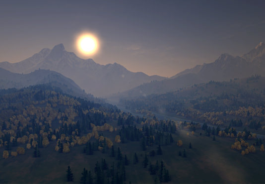
Realistic atmospheric scattering is one of the nuances, having tremendous impact on the visual convincingness. The atmosphere is filled with small particles (such as dust, water or ice crystals) that scatter and absorb light. This phenomenon is known as atmospheric scattering. It is responsible for changing the sunlight from the pale red at dawn to bright yellow at noon and back again. It also determines the color of the sky and gradual attenuation of distant objects. All these visual effects differ depending on the atmospheric conditions, air pollution and other factors. It should be taken into account, that while the minor variances are intuitively deemed natural, presenting some alien planet should aim for scattering parameters significantly dissimilar to the Earth's ones. They can be adjusted on the Scattering tab of Render settings.
Shadows
As the world light source is designed to illuminate really large spaces, usage of the usual shadow map is memory-ineffective. The parallel-split shadow mapping technique substantially optimizes the generation of shadows casted by this source. For more detailed information refer to the PSSM article.
Range
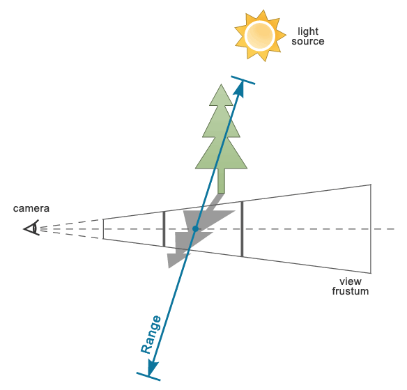
A credible scene requires setting the appropriate range for the shadow-casting geometry (see the article about PSSM). To estimate the needed value, orient on the highest objects included in the scene. Otherwise, when out of view but still near-standing, they are excepted by rendering shadows and mess up the anticipated scene shadowing pattern.

Splitting
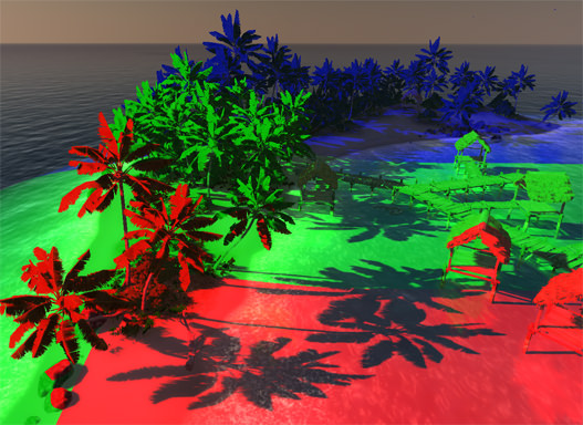
Subdividing a scene surface into splits with different shadow maps is the essence of PSSM method improvement. Each split requires a separate rendering pass. All the split maps have the same resolution corresponding to the map size parameter, but are applied to different areas. Thus, close-range shadows are of higher quality and distant ones of lower.
- Defining only one shadow split results in having fuzzy and on the whole hardly satisfactory shadows. Load on video card memory is minimal, however.
- The maximum of four splits contributes to the both visually expressive and performance efficient shadowing and enhances the rendered image quality, though rendered in four passes.
Distribution
The shadow splits distribution allows to accurately adapt the quality of the shadows depending on their remoteness from the viewer. The redistribution is performed within the available shadow distance specified in Render settings.
- Decreasing the value generates splits that are smaller, more compact positioned and cover less distance. But at the same time, the resulting shadows are of a higher quality.
- Increasing the value ensures the larger splits with broader coverage of the area. Yet the side effect of the shadow quality deterioration should be kept in view.


