Entity-Related Properties
Each time you add a new model representing an entity to the world you should assign all necessary properties and adjust their parameters to ensure proper integration into the simulation environment.
Before you start configuring properties, check that all pivot axes for the model are set properly:
- The main pivot for the aircraft model should be set close to its center, with X axis pointing to the right and Y axis pointing forward.
- Horizontal parts should have their pivot axes oriented along the +X (left-to-right relative to the plane), while vertical ones — along the +Z (bottom-to-top). Initial rotation angles of parts do not matter, important is that they should be in neutral position: extended — for gears, and retracted — for flaps.
See Also#
- Aircraft add-on with a set of ready-to-use aircraft components
Model Simplification#
The Simplifier component can help optimize rendering of your entities. This component, when assigned to an entity, enables you to define which parts of its model can be neglected starting at certain distance levels (e.g., hide flaps, ailerons, and rudders at 1km, engines at 5 km, etc.) and which substitutes can be used to represent an entity at a large distance (e.g., a flashing strobe light, when the plane is just a point on the screen).
Basically there are 3 layers of LODs:
- Surfaces Layer — UNIGINE's standard LOD System
- Simplifier Nodes — when nodes change their enabled flag and detached from parent
- Billboard Nodes — whole nodes become disabled (hidden) and only substituting billboards are shown
To configure model simplification, assign a property inherited from the Simplifier to the node, and indicate which nodes are to be hidden at which distance, and when to substitute your model with an impostor:
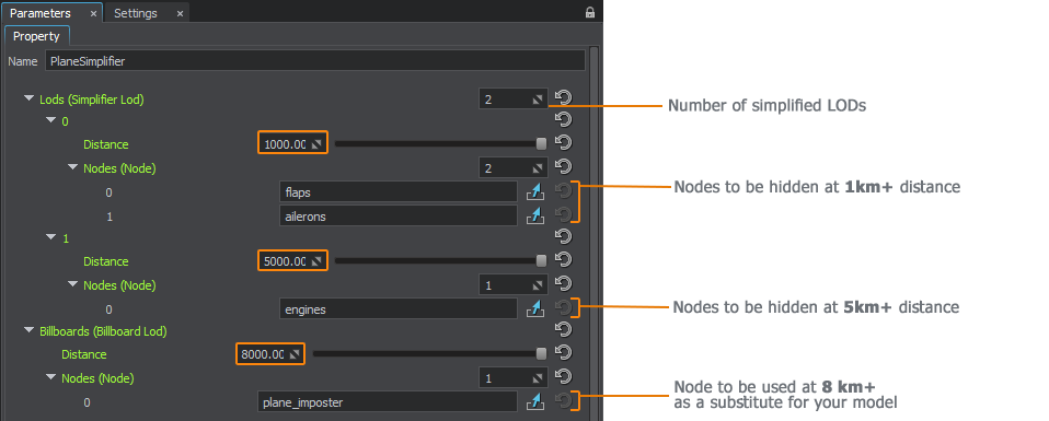
Surface LODs can be combined with Simplifier LODs:
- At a distance of 1000 and closer, flaps are represented by separate meshes.
- If the plane is at a distance of 1000+, we can hide all flaps and enable a surface LOD for wings with flaps.
The last Billboard node replaces all model's geometry at a certain distance.
The Simplifier component has its own distance scale value which enables quick tuning of the simplification process while balancing between quality and performance.
Prespawned Entities#
You can create entities not only from code, but via UnigineEditor as well. This is achieved by assigning the EntityComponent property to an object. The entity in this case will already exist in the world, and all settings attributable to its type will be uploaded on the world load.

Wheels#
The Wheel property is intended for wheels or groups of wheels to fine-tune their behavior to make them look more natural:
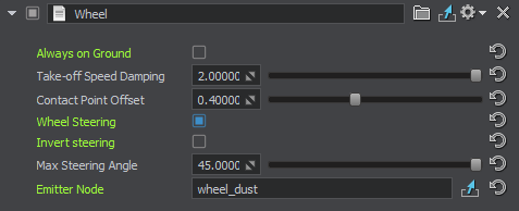
- Always on Ground — is used for optimization: if the vehicle is not intended to fly, it doesn't require any ground contact checks, therefore some effort can be saved.
- Take-off Speed Damping — gradual slowing down of the wheel rotation after take-off to avoid its abrupt stop that looks unnatural.
- Contact Point Offset — the value (in meters) that allows fine-tuning the ground contact point for the wheel.
- Wheel Steering — enables automatic steering of the wheel at the vehicle turning without any additional coding. You can also make the wheel rotate to the opposite direction by using the Invert Steering parameter and set the required Max Steering Angle.
- Emitter Node — a node that emits particles to create a certain effect such as dust, mud, or splashes generated by the wheels.
The ground contact check is fine-tuned via the WheelControl property that allows setting the update period for this check in times per second:

Wheel Trace Decal#
The WheelTraceDecal property is intended for rendering the wheel trace. The input can be obtained from the host, code, or anything else. The usage example of this property is available in the Aircraft addon. The wheel trace in the addon can be generated automatically or via host command.
To set up the wheel trace:
-
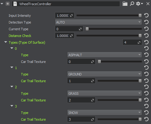
To make wheel traces differ depending on the surface type (asphalt, ground, snow, etc.), assign the WheelTraceController property to the parent node (vehicle) and define the surface type for each wheel trace texture. Set the surface type via code for each surface so that it would switch automatically, or control it manually via host.
-
Assign the WheelTraceDecal property to each node representing the wheel.
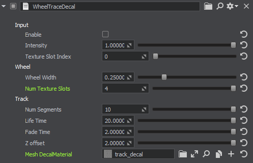
The following property parameters are available:
- Enabled — toggles the trace rendering. This is the default value that can be changed at runtime.
- Intensity — the trace intensity value. With the minimum value of 0 the trace is completely invisible. With the maximum value of 1 — completely visible. This is the default value that can be changed at runtime.
- Texture Slot Index — index of the vertical texture slot in the texture atlas to be set for the trace. This is the default value that can be changed at runtime.
- Wheel width — the width of the wheel.
- Num Texture Slots — total number of the vertical texture slots (slices into which the texture can be divided) that represent visualization of the trace on various surfaces.
- Num Segments — the maximum number of segments in one Mesh Decal. A segment is a quad with the side equal to the wheel width. As soon as this number is reached, Mesh Decal is created.
- Life Time — the period during which the Mesh Decal containing the trace is visible.
- Fade Time — the period during which the Mesh Decal containing the trace gradually disappears.
- Z offset — the decal offset above the landscape (the default value of 2 is suitable for most cases).
- Mesh Decal Material — the Mesh Decal material.
Aircraft Lights#
This section contains actions to be performed for controlled aircraft lights (landing, taxi, beacon, navigation, etc.).
- Assign the LightAircraftController property to the parent node (aircraft) and leave all parameters unchanged.
-
Assign the LightAircraft property to each node representing aircraft lights of various types.
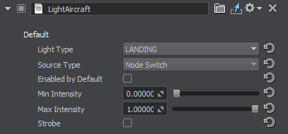
- Set up the light parameters.
Aircraft Lights Control#
Aircraft lights are controlled automatically by the IG. In case you implement some custom IG logic, you can control lights of an aircraft via code as follows:
Aircraft lights control example:
// getting an aircraft entity by its ID (see data/ig_config.xml)
Entity *entity = ig_manager->getEntity(__entity_id__);

// getting a property for the component by its ID (see data/ig_config.xml)
PropertyPtr p_light_outer = entity->getComponent(__component_id_from_config__)->getProperty();

// enable all lights (landing, taxi, etc.) for the aircraft
p_light_outer->getParameterPtr("landing")->setValueToggle(1);
p_light_outer->getParameterPtr("taxi")->setValueToggle(1);
p_light_outer->getParameterPtr("navigation")->setValueToggle(1);
p_light_outer->getParameterPtr("beacon")->setValueToggle(1);
p_light_outer->getParameterPtr("strobe")->setValueToggle(1);
p_light_outer->getParameterPtr("logo")->setValueToggle(1);Lights#
Lights available in the scene and not referring to any aircraft can also be controlled.
It is possible to control lights manually by assigning LightSourceComponent to them or automatically depending on time of day — in this case AutomaticTimeLightingComponent should be used.
Interaction with Water#
For objects and entities that are able to float on water, the WaterClamp property is available.

The following parameters are available:
- Clamp Enable — enabling the option identifies that the entity has the possibility to interact with the water surface (float on it), which is implemented according to IG commands. The Forced value makes the entity always be clamped to the water surface, which is suitable for boats, for example.
- Point Front Center — front waterline point.
- Point Back Left — rear left waterline point.
- Point Back Right — rear right waterline point.
- Intertia — relative weight value: the more the value, the heavier the object seems.
The following adjustments should be done to make water clamping work properly:
- Intersection Mask of the Global Water object should be enabled and correlate with the IG terrain_intersection_mask.
-
The entity should have the Ground Clamp attribute set to one of the following values:
- NON_CONFORMAL — the entity takes into account only the water height.
- CONFORMAL — the entity takes into account both the height and the normals of the water surface.
Synchronization#
When running IG with Syncker, it is required to synchronize entities to have their movements displayed both on the master and slave computers. This can be done either via code (Master::addSyncNode()), or using the property: in the Editor, assign the AddSyncNode property to the nodes that should be synchronized.