Generating Roads
Roads are generated by tiling a decal created from a basic static mesh along the vector data available.
Let's review the basic workflow.
1. Preparing a Basic Object#
First, we create an ObjectMeshStatic, that will be used as a building block for generation.
-
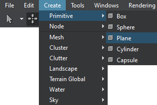
Create a mesh (we use a plane for the road here): on the Menu Bar, click Create —> Primitive —> Plane.
-
Specify the mesh parameters. For our road we set the following:
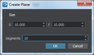 NoticeIt is recommended to use more than a single segment to make road curves smoother.
 -
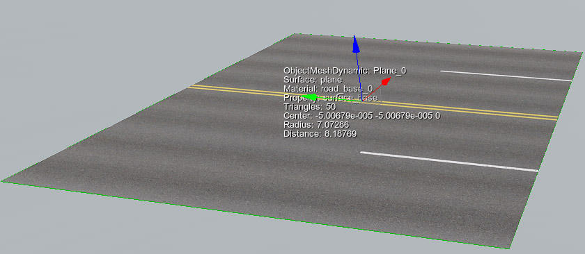
Inherit a material from the mesh_base, set all necessary textures and parameters and assign it to the mesh.
-
The road is generated by means of tiling of the basic mesh along one of the axes X, Y or Z (forward axis), so make sure that your mesh is oriented properly — in this case the forward axis is X (red arrow).
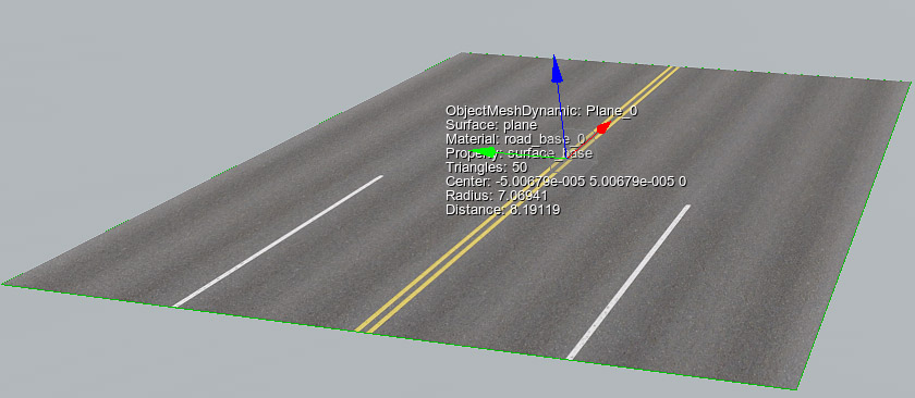
-
Geometry is very resource consuming. Thus, to maintain acceptable performance you should set up LODs for the basic mesh. For each surface of the mesh specify visibility and fade distances. These settings will be used for managing LODs of generated spline objects.
For more information on LOD settings see Setting Up Object LODs.
-
Move the mesh to the origin and export it to a .node file.
Now the basic node for roads (the *.node asset) is ready to use and you can delete it from the scene.
2. Adding a Vector Data Source#
Currently, Sandworm allows using only offline vector data source for generation.
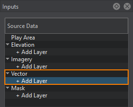
- In the Source Data panel, add a new vector data layer.
- In the Parameters panel, define the type of Data Source to be used: Assets or External Files. Currently only *.shp and *.geojson are supported as assets. Therefore, if you have other types of files, you can try to add them as External Files.
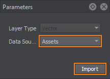
Click Import. - In the window that opens, select the set of files to be used as vector data.
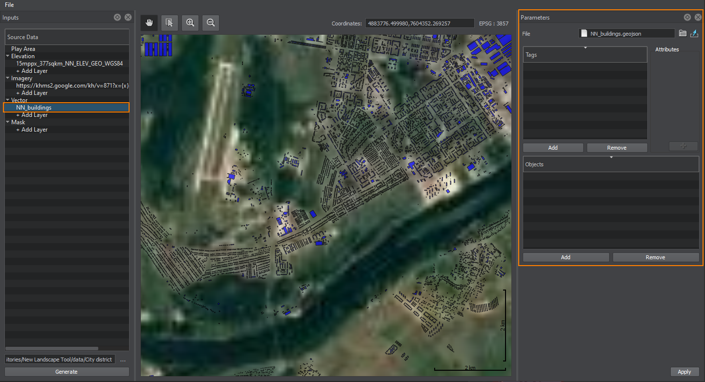
When the vector data is added, its image is displayed atop all the layers in the Preview panel (the order of layers display may be changed), and the Vector layer parameters become available.
3. Specifying Tags to Filter Vector Data#
The Tag is in fact a set of rules used to pick the specific data from the list of all available vector data. The rules are created using the Attributes. Only the objects that fit to the requirements of every attribute are generated based on this tag.
Tags are created as follows:
-
Click the Add button in the Tags window in the Parameters panel.
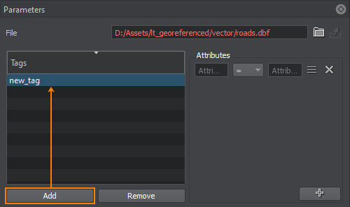
Double-click on the tag to specify a tag name. To remove a tag use Remove button. -
For each tag, set an attribute (or attributes) to filter certain data from the vector source. The required data is filtered using the attribute value and suitable operator. Autocomplete is available. You can type in attribute names and values or select them from the attribute list.
The available operators are: =, !=, >, <, ANY. ANY generates all the objects that have any value assigned for the selected attribute.
You can also select attribute values from the Attributes table. The table opens using the sign on the right of the attribute expression.

-
To add more attributes, use the "+" (plus) button. You can add as many attributes for one tag as necessary.
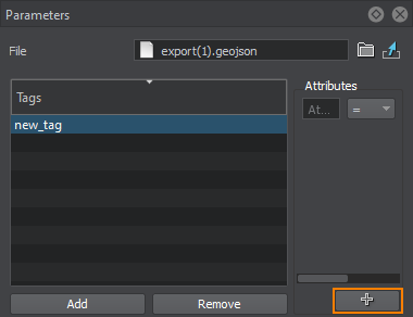 NoticeIf several attributes are set, only the data that comply with all the attributes will be selected.
To remove a filter, use the button to the right of the attribute expression.
4. Specifying Parameters of Vector Objects#
In this step, we are going to set objects that will be generated and placed across the surface of the terrain according to the data filtered by the tag.
In the Objects window, click Add to add the object that will be generated on the terrain based on the vector data specified for it. The dialog window will open:
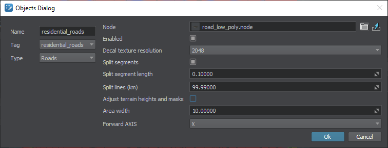
Set the following object parameters:
| Name | The object's name, which is displayed in the Objects list in Sandworm and in World Nodes when the terrain is generated. |
|---|---|
| Tag | The tag for the selected object from the list of created tags. In this case, we select Roads. |
| Type | Type of the vector object to be generated. In this case, we are generating Roads. |
| Node | The path to the basic object's *.node file. |
| Enabled | When toggled on, the objects of this type will be generated. When toggled off, the objects of this type are not generated and won't exist in the world containing the generated terrain. |
| Decal texture resolution | Resolution of the baked texture for decals. Notice Available only for decal type. |
| Split segments | Flag indicating whether the segment splitting mode is enabled. In this mode all segments will be divided into subsegments of the specified length (if this length does not exceed the length of the segment itself). Notice This parameter can be used to provide better alignment of decals with the terrain. |
| Split segment length | Length of the segment for splitting mode, in units. Notice The lower the value the more segments will be generated. Setting too low values may significantly reduce performance. |
| Split lines (km) | Flag indicating whether line splitting mode is enabled. By default a single decal object shall be generated for the specified tag and shall include all relevant decals. When line splitting mode is enabled the line will be divided into parts of the specified length (if this length does not exceed the length of the line itself). Each part will be represented by a separate decal object. |
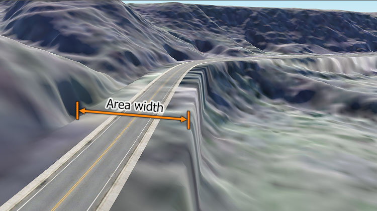
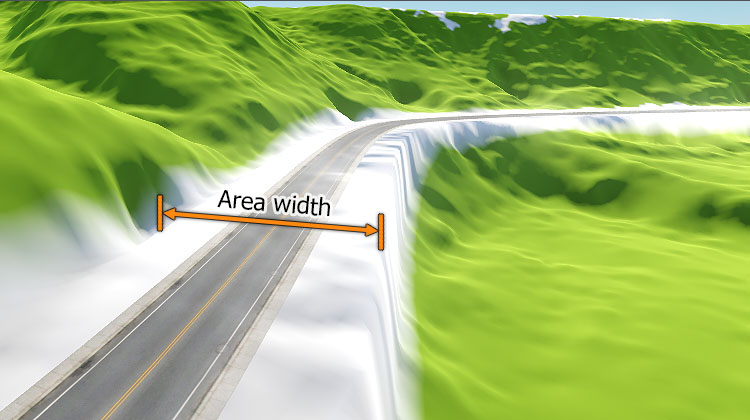
| Adjust terrain heights and masks | Flag indicating whether terrain heights and masks will be adjusted for generated roads. When this option is enabled the following data of the terrain will be modified in the areas along the roads (vector data) having the width specified by the Area width parameter:
Notice
|
| Area width | Width of the area along the spline to be affected by heights and masks adjustment.
Notice
Available only when heights and masks adjustment is enabled. |
| Forward axis | Axis along which the basic mesh is to be extruded or tiled. |
4. Generating Roads#
Now you need to configure the output settings and generate (or regenerate) roads on the terrain by clicking the Generate button.
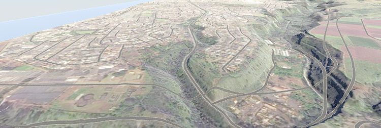
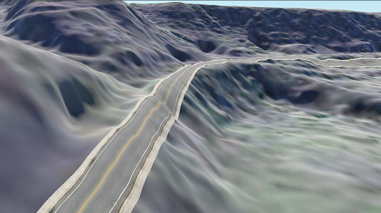
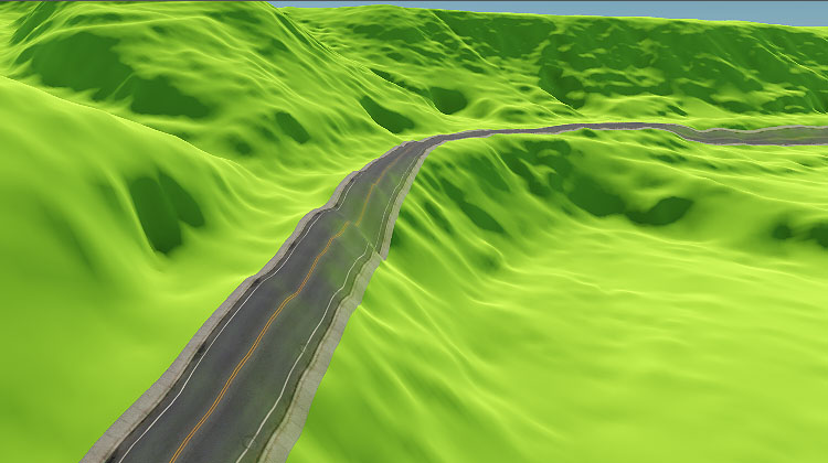
A terrain fragment with roads generated on the basis of vector data using the basic mesh object we created:
