Mesh Class
The Mesh class provides an interface for mesh loading, manipulating and saving.
By using this class, you can create a mesh, add geometry to it (e.g. box, plane, capsule or cylinder surface), add animations and bones (if you want to create a skinned mesh) and then use it to create the following objects:
Also you can get geometry of all of these objects via the Mesh class.
Features of the mesh are listed below:
- Each surface of the mesh supports several morph targets.
- Each surface has a quaternion-based tangent basis for the better loading speed.
- 8-bit vertex colors are supported.
- Each vertex of a surface has 2 sets of indices: coordinate and triangle indices. It improves the loading speed and reduces data duplication.
- Each vertex of a surface has 2 UV sets.
-
A bind pose transformation is stored for each mesh (even if there are no animations and animation frames). See also the getBoneTransforms() function.
NoticeThe 1st animation frame should not contain the bind pose.
Vertex Data and Indices#
Each surface of the mesh consists of triangles, and each triangle has 3 vertices. Thus, for each mesh surface we have:
Total number of vertices = 3 * number of triangles.
If a vertex belongs to several triangles, we have to store several copies of such vertex. Each of these copies would store information about position, normal, binormal, tangent and texture coordinates. In order to reduce data duplication and increase loading speed UNIGINE uses the optimization described below.
There are 2 separate vertex data buffers:
- CVertices coordinate buffer, which stores only vertex coordinates.
- TVertices triangle buffer, which stores vertex attributes such as normal, binormal, tangent, color, UV coordinates.
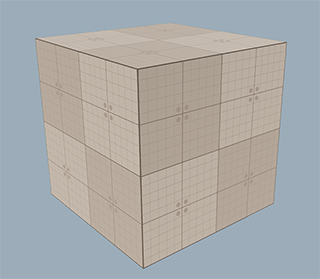
On the picture below, arrows are used to show normals:
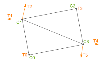
The coordinate buffer is an array of coordinate vertices. In order to reduce data duplication, vertices of surface which have the same coordinates are saved only once in the buffer. For example, the coordinate buffer for the surface presented on the picture above is the following:
CB = [C0,C1,C2,C3]Each polygon of the surface has 3 coordinates. We have 2 polygons, thus, we have 6 vertices, but we save in the CVertices buffer only 4, because 2 of them have the same coordinates. Each coordinate vertex contains coordinates (float[3]) of the vertex.
The triangle buffer is an array of triangle vertices. For example, the triangle buffer for the surface presented on the picture above is the following:
TB = [T0,T1,T2,T3,T4,T5]Each triangle vertex can store:
- Normal
- Binormal
- Tangent
- 1st UV map texture coordinates
- 2nd UV map texture coordinates
- Color
The number of triangle vertices depends on the number of triangles, to which the vertex belongs. For example, if 2 triangles have 1 adjacent vertex with different normals for each triangle, 2 triangle vertices will be stored (the 1st and the 3rd vertices on the picture above). However, if the components are the same for all of the adjacent triangles, only 1 triangle vertex will be stored.
Both the coordinate and triangle vertices have indices. There are 2 index buffers to get proper cvertex and tvertex data for each vertex of each triangle of the mesh:
- CIndices buffer — coordinate indices, which are links to CVertices data.
- TIndices buffer — triangle indices, which are links to TVertices data.
The number of elements in these index buffers is equal to the total number of vertices of a mesh surface.
Coordinate Indices#
Each vertex of a mesh surface has a coordinate index - a number of the corresponding element of the coordinate buffer, where the data is stored. For the given surface the array of the coordinate indices is as follows:
CIndices = [Ci0,Ci1,Ci3,Ci1,Ci2,Ci3]Here:
- The first 3 elements are the coordinate indices of the first (bottom) triangle.
- The second 3 elements are the coordinate indices of the second (top) triangle.
Triangle Indices#
Each vertex of a mesh surface also has a triangle index - a number of the corresponding element of the triangle buffer, where the data is stored. For the given surface the array of the triangle indices is as follows:
TIndices = [Ti0,Ti1,Ti5,Ti2,Ti3,Ti4]Here:
- The first 3 elements are the triangle indices of the first (bottom) triangle.
- The second 3 elements are the triangle indices of the second (top) triangle.
See Also#
- Article on Mesh File Formats.
- Description of the Mesh class functions.
Accessing a Mesh of a Mesh-Based Object#
You can access a Mesh of a mesh-based object (e.g. a static mesh, a skinned mesh and so on) via the getMesh() method of the corresponding object class.
For example, to access the Mesh of the ObjectMeshStatic, you can do the following:
Copying a Mesh#
You may need to copy a Mesh in the following cases:
- When you have a mesh-based object that should be copied into another mesh-based object (new or existing one).
- When you have a Mesh that should be copied into another Mesh.
From One Mesh to Another#
You can easily copy the existing mesh instance to a new one: pass the mesh instance as an argument to the constructor as follows:
Accessing Mesh Surfaces#
By using the Mesh class, you can add new surfaces to a mesh or copy surfaces from one mesh to another.
Adding a New Surface to a Mesh#
You can add a new surface to a mesh in one of the following ways:
- Create a surface from scratch and then add verties and indices to it.
- Create a surface using one of the existing predefined surfaces: a plane, a prism, a sphere, a box, a capsule, a cylinder, a dodecahedron, an icosahedron.
Creating a Surface from Scratch#
The Mesh class allows creating a surface and adding vertices to it.
In the following example, we create a plane by adding vertices to the mesh:
- Create a Mesh class instance, add a surface and 4 vertices to it.
- Add 6 indices to create a plane.
NoticeYou can add indices explicitly as in the example below, or you can create indices for recently added vertices by using the createIndices() function.
- Create tangents and normals by using the createTangents() and createNormals() functions.
- Update bounds of the mesh to include all new vertices via the createBounds() function.
- Create an ObjectMeshDynamic instance using the mesh to check the result.
Adding a Predefined Surface#
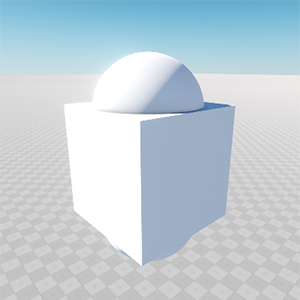
To add a predefined surface to a Mesh instance, use the required function. For example, to add a new capsule surface to a mesh, do the following:
- Create a Mesh class instance.
- Add a capsule surface via the addCapsuleSurface() function.
- Create an ObjectMeshDynamic instance using the mesh to check the result.
Copying Surfaces from One Mesh to Another#
In the following example, we create two meshes with different surfaces. The first mesh has the capsule surface, the second has the box surface. We copy the box surface from the second mesh to the first. The execution sequence is:
- Create 2 instances of the Mesh class and add the capsule and box surfaces to them.
- Add the box surface from the second mesh (mesh_1) to the first mesh (mesh_0) by using the addMeshSurface() function.
- Create a new ObjectMeshDynamic mesh from the mesh_0 instance.
// create mesh instances
Mesh mesh_1 = new Mesh();
Mesh mesh_2 = new Mesh();

// add surfaces for the added meshes
mesh_1.addCapsuleSurface("capsule_surface", 1.0f, 2.0f, 200, 100);
mesh_2.addBoxSurface("box_surface", Vec3(2.2));

// add the surface from the mesh_2 to the mesh_1 as a new surface
// with the name "new_box_surface"
mesh_1.addMeshSurface("new_box_surface", mesh_2, 0);

// create the ObjectMeshDynamic from the mesh_1 object
ObjectMeshDynamic dynamicMesh = new ObjectMeshDynamic(mesh_1);

// set the position of the mesh
dynamicMesh.setWorldTransform(translate(Vec3(10.0f,10.0f,10.0f)));
// set the name of the mesh
dynamicMesh.setName("Dynamic Mesh");
In the result, the Mesh will have 2 surfaces.
The ObjectMeshDynamic mesh will appear in the editor:
Adding a Surface to the Existing Mesh#
In the following example, we add a surface to the existing mesh and then add necessary vertices and indices for the surface:
- Create a new mesh instance from the file.
- Add a new surface to the mesh.
- Add vertices for the mesh surface.
- Create indices for recently created vertices by using the createIndices() function.
- Update bounds of the mesh to include the created surface by using the createBounds() function.
- Change the surface color.
In the example, the box.mesh file has been taken from the UNIGINE SDK Samples. However, you can create a box mesh and save it to a file as follows:
// create an empty Mesh instance
Mesh box = new Mesh();
// add a box surface to the Mesh
box.addBoxSurface("surface_box", Vec3(1.0f));
// save the box to a file
box.save("unigine_project/meshes/box.mesh");// load a mesh form the file
Mesh mesh = new Mesh("unigine_project/meshes/box.mesh");
// add a new surface
mesh.addSurface("surface_triangle");
// add 3 vertices to the new surface
mesh.addVertex(Vec3(-0.5f, 0.5f, 0.5f), 1);
mesh.addVertex(Vec3(-0.5f, -0.5f, 0.5f), 1);
mesh.addVertex(Vec3(-0.5f, -0.5f, 1.5f), 1);
// create indices for the new surface
mesh.createIndices(1);
// create a new boundbox for the mesh including new surface
mesh.createBounds();
// save mesh to file
mesh.save("unigine_project/meshes/box_2.mesh");
// create ObjectMeshStatic from the Mesh object
ObjectMeshStatic staticMesh = new ObjectMeshStatic("unigine_project/meshes/box_2.mesh");
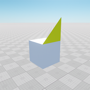
// prepare a material for the added surface
Material mesh_base = engine.materials.findMaterial("mesh_base");
Material material = mesh_base.inherit("mesh_base_yellow", "unigine_project/materials/mesh_base_yellow.mat");
material.setParameter(MATERIAL_PARAMETER_COLOR, Vec4(255, 255, 0, 255));
// set the position of the mesh
staticMesh.setWorldTransform(translate(Vec3(10.0f, 0.0f, 2.0f)));
// set the material to the mesh surfaces
staticMesh.setMaterial("mesh_base", 0);
staticMesh.setMaterial("mesh_base_yellow", 1);The triangle surface added to the mesh:
Changing Vertex Attributes#
The Mesh class allows changing vertex attributes.
In the following example, we take a plane and change attributes of its vertices:
- Create a Mesh and add a new surface to it.
- Print the current normal values of 2 vertices to the console.
- Set new values for the normals and print the updated values to the console.
- Print the current tangent values of 2 vertices to the console.
- Set new values for the tangents and print the updated values to the console.
- Create a new ObjectMeshDynamic from the Mesh instance to check the result.
// create a mesh instance
Mesh mesh = new Mesh();

// add a new surface
mesh.addSurface("surface_0");

// add vertices of the plane
mesh.addVertex(Vec3(0.0f,0.0f,0.0f),0);
mesh.addVertex(Vec3(0.0f,0.0f,1.0f),0);
mesh.addVertex(Vec3(0.0f,1.0f,0.0f),0);
mesh.addVertex(Vec3(0.0f,1.0f,1.0f),0);

// add indices
mesh.addIndex(0,0);
mesh.addIndex(1,0);
mesh.addIndex(2,0);

mesh.addIndex(3,0);
mesh.addIndex(2,0);
mesh.addIndex(1,0);

// create tangents
mesh.createTangents();

// create mesh bounds
mesh.createBounds();

// create normals
mesh.createNormals();

// show the message in console about the normals of the first
// and the second normal before changing
log.message("the first normal is: %s and the second is: %s\n", typeinfo(mesh.getNormal(0, 0, 0)), typeinfo(mesh.getNormal(1, 0, 0)));

// set the new value of the normals
mesh.setNormal(0, Vec3(1,1,0), 0, 0);
mesh.setNormal(1, Vec3(1,1,1), 0, 0);

// show the normals value in the console
log.message("the first normal is: %s and the second is: %s\n", typeinfo(mesh.getNormal(0, 0, 0)), typeinfo(mesh.getNormal(1, 0, 0)));

// show the tangent value in the console
log.message("tangent is: %s\n", typeinfo(mesh.getTangent(0,0,0)));

// set the new value of the tangent
mesh.setTangent(0, quat(0.0,-0.0,-0.0,1), 0,0);

// show the tangent value after the changing the value
log.message("tangent is: %s\n", typeinfo(mesh.getTangent(0,0,0)));

// create the ObjectMeshDynamic from the Mesh object
ObjectMeshDynamic dynamicMesh = new ObjectMeshDynamic(mesh);

// set the position of the mesh
dynamicMesh.setWorldTransform(translate(Vec3(10.0f,10.0f,10.0f)));
// set the name of the mesh
dynamicMesh.setName("new_mesh");
When you launch the project, in the console you'll see the following:
the first normal is: vec3: -1 0 0 and the second is: vec3: -1 0 0
the first normal is: vec3: 1 1 0 and the second is: vec3: 1 1 1
tangent is: quat: 0.5 -0.5 -0.5 0.5
tangent is: quat: 0 0 0 0.999962
When setTangent() and setNormal() functions were called, the normal and the tangent changed their values.
Let's comment this part of the code:
// show the tangent value in the console
log.message("tangent is: %s\n", typeinfo(mesh.getTangent(0,0,0)));

// set the new value of the tangent
mesh.setTangent(0, quat(0.0,-0.0,-0.0,1), 0,0);

// show the tangent value after the changing the value
log.message("tangent is: %s\n", typeinfo(mesh.getTangent(0,0,0)));
The result will be different. You can see what influence the tangent has on the vertex:
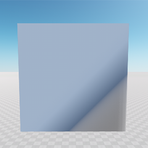 |
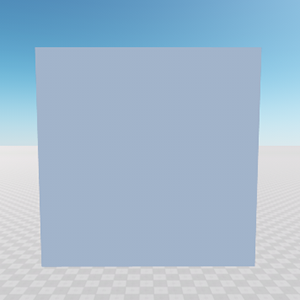 |
Plane with changed tangent |
Plane with unchanged tangent |
Creating a Primitive#
The following example shows the manual creation of a box primitive by specifying its vertices, normals and texture coordinates:
// the size of a box
Vec3 size = Vec3_one;

// array of vertices
Vec3 vertex[8] = (
	Vec3(-0.5f, -0.5f, -0.5f), Vec3(0.5f, -0.5f, -0.5f), Vec3(-0.5f, 0.5f, -0.5f),
	Vec3(0.5f, 0.5f, -0.5f), Vec3(-0.5f, -0.5f, 0.5f), Vec3(0.5f, -0.5f, 0.5f),
	Vec3(-0.5f, 0.5f, 0.5f), Vec3(0.5f, 0.5f, 0.5f)
);

// array of face normals
Vec3 normals[6] = (
	Vec3(1, 0, 0), Vec3(-1, 0, 0),
	Vec3(0, 1, 0), Vec3(0, -1, 0),
	Vec3(0, 0, 1), Vec3(0, 0, -1)
);

// array of texture coordinates
Vec2 texcoords[4] = (
	Vec2(1.0f, 1.0f), Vec2(0.0f, 1.0f),
	Vec2(0.0f, 0.0f), Vec2(1.0f, 0.0f)
);

// list of indices for 6 polygons
Vec4 cindices[6] = (
	Vec4(3, 1, 5, 7), Vec4(0, 2, 6, 4),
	Vec4(2, 3, 7, 6), Vec4(1, 0, 4, 5),
	Vec4(6, 7, 5, 4), Vec4(0, 1, 3, 2)
);

// list of indices for a single quad made of 2 triangles
int indices[6] = (
	0, 3, 2, 2, 1, 0
);

// create a mesh instance
Mesh mesh = new Mesh();

// add a new surface
mesh.addSurface("box");

// cycle through all quads
for (int i = 0; i < 6; i++)
{
	// cycle through all indices of a single quad
	for (int j = 0; j < 6; j++)
	{
		int index = indices[j];
		mesh.addVertex(vertex[cindices[i][index]] * size, 0);
		mesh.addNormal(normals[i], 0);
		if (i == 4)
		{
			mesh.addTexCoord0(Vec2(1, 1) - texcoords[index], 0);
		} else
		{
			mesh.addTexCoord0(texcoords[index], 0);
		}
	}
}

// create indices per each 3 added vertices
mesh.createIndices(0);

// create tangents
mesh.createTangents(0);

// create mesh bounds
mesh.createBounds(0);

// create the ObjectMeshDynamic from the Mesh object
ObjectMeshDynamic dynamicMesh = new ObjectMeshDynamic(mesh);

// clear the mesh pointer
mesh.clear();

// set the name of the mesh
dynamicMesh.setName("new_mesh");

// set the position of the mesh
dynamicMesh.setWorldTransform(translate(Vec3_zero));

// set the checker albedo texture
dynamicMesh.setMaterialTexture("albedo", "core/textures/common/checker_d.dds", 0);