Creating a Terrain
The Landscape Tool allows creating a terrain based on ordinary raster images (with no geodata). Follow the steps described in the chapters below to generate the terrain.
See Also
- Creating a Geo-Referenced Terrain article if you need to:
- Create a terrain based on the real geodata sources.
- Create a terrain based on both the ordinary images and geodata sources.
1. Specifying Data Sources#
The data sources should be specified before proceeding.
 dedicated tutorial.
They are divided into five types (layers), however, only the following support loading the raster images with no geodata:
- Height (Elevation) (optional) - this type of data is used to generate terrain geometry. Here the height maps of the R8, R16 or R32f format should be loaded.NoticeThe indexed black-and-white data sources are interpreted as RGB images, so they cannot be used for the elevation data sources.
- Albedo (Imagery) - this type of data is used to generate textures for the terrain surface. Here the albedo textures of the RGB8/16/32f and RGBA8/16/32f formats should be loaded. Alpha-channel in the second case is used to mark "no data" areas.
- Masks (Landcover) (optional) - this type of data is used to generate natural features of the landscape (details, grass, trees, etc.). Here the detail masks the R8/16/32f or RGB8/16/32f formats should be loaded.
To add a new source, click the Add Source button.
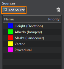
In the opened window, specify the following fields:
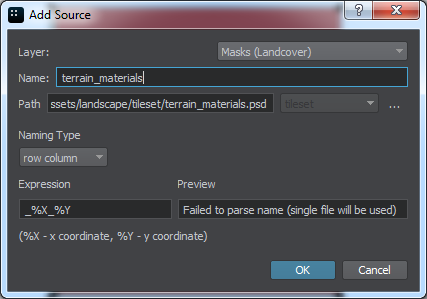
| Layer | The albedo, height, masks or procedural layer of the data source. | ||||
|---|---|---|---|---|---|
| Name | The name of the layer that will be displayed in the Sources panel. | ||||
| Path | The path to the data source file(s). The data source can be represented as a single raster image or as a source tileset (a set of raster images). In the second case, the first file of the source tileset should be specified: the other files will be detected in the same folder automatically according to the Naming Type and Expression values. The following formats are supported: .png, .tif, .jpg, .psd, .dds, .tga. To specify the path, click the ... button.
Notice
The source tileset isn't related to the tileset used for the generated terrain. Notice
Do not store the data source files in the data folder of the project as it will cause the following issues:
|
||||
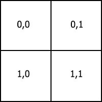
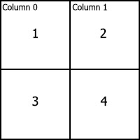
| Naming Type | The source tileset layout type. The following values are available:
|
||||
| Expression | A regular expression string used to find files that should be loaded for the source tileset and to determine its indices (or rows and columns, depending on the Naming Type):
|
||||
| Preview | Shows the index (or the row and column) of the first file and the total number of the files added to the source tileset. |
The files of the source tileset (except the first one specified in the Path field) will be automatically detected and loaded according to the values described above.
For example, to load the source tileset that contains 4 tiles, you can name them as follows: Tile_0-0.png, Tile_1-0.png, Tile_0-1.png, Tile_1-1.png. And then perform the following:
- Specify the Tile_0-0.png as the first file of the source tileset.
- Choose the row column layout.
- Specify the _%X-%Y expression.
When you add the imagery, elevation, landcover or procedural data sources to the Landscape tool, their areas will be highlighted on the Preview panel with corresponding colors: blue for elevation, green for imagery, red for landcover and magenta for procedural. Area size of procedural sources is adjustable.
The minus sign button deletes selected data source.
2. Specifying Data Source Parameters#
When you select the loaded data source, you can see its parameters in the Parameters panel.
Elevation Parameters#
Imagery Parameters#
The parameters are the same as for the elevation source (except Tileset Elevation Settings). You can also specify the following parameter:
| No data color | The color to be used for areas with no data available. |
|---|
Landcover Parameters#
Landcover data source parameters are described here. This type of data source is optional and should be added when generation of terrain details or vegetation is needed.
Procedural Parameters#
Procedural data source parameters are described here. This type of data source is optional and should be added when it is necessary to refine data from elevation, landcover or other procedural data sources.
3. Setting Up Natural Layer#
At this step you can check out the parameters of Terrain LODs to be generated for all data layers (elevation, imagery, normal, and detail masks) and determine the natural features of the landscape.
LOD Settings#
To access LOD settings of the particular data layer of your terrain, select the data source group in the list: all available settings will be displayed on the Parameters panel.
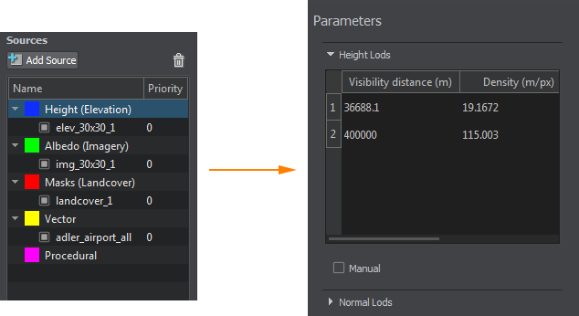
The Landscape Tool sets the number of LODs, their visibility distances and densities automatically. You can change these settings when necessary. To modify LOD settings for the desired data layer you should set Manual mode by checking the corresponding option located just under the list of LODs (see the picture below).
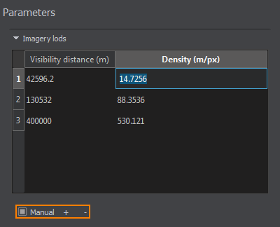
In the manual mode you can modify density and visibility distance values by simply double-clicking on the corresponding cell and entering the desired value. Use + (plus) button to add a LOD, or - (minus) to remove one.
Natural Features#
You can also determine, which natural features of the landscape are to be generated: select the Masks (Landcover) data source type and get access to the following settings on the Parameters panel:
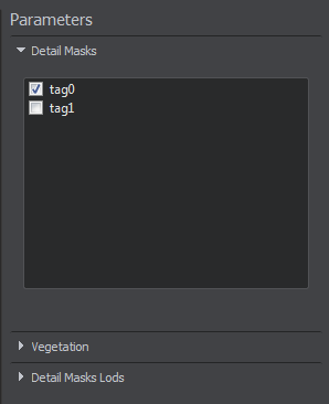
-
Terrain detail masks - the tags specified for landcover data sources that determine the areas for terrain details to be placed.
Workflow: Generating Detail Masks.
-
Vegetation (grass, trees, etc.) - Grass, Mesh Clutter, and World Clutter objects will be generated and placed in certain areas of the terrain according to specified landcover tags.
Workflow: Generating Vegetation.
4. Specifying Settings#
Landscape tool generates a terrain according to the specified settings. Set the following parameters before starting terrain generation:
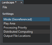
Modes and Projections#
To generate the terrain based on the raster images with no geodata, the Flat mode should be set. In this mode, no reprojection is performed for the loaded data sources.
Play Area#
Play Area is a rectangular area of a landscape to be generated.
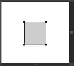
Play Area represents a gray outlined rectangular area in the Preview panel.
Click on the Play Area settings. In the Parameters panel the available parameters for Play Area will appear:

You can specify the following parameters:
| Center | The central point coordinates of the Play Area. |
|---|---|
| Size (km) | The size of the Play Area: width x height. Notice The size should coincide the Largest size values set for the data sources. If the Play Area too large, the generated terrain may be outlined with the grey area. |
| Max visibility distance (km) | The maximum visibility distance of the Play Area in kilometres. |
Processing Priority#
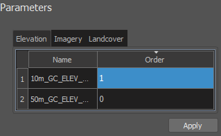
Here you can specify the order in which data sources will be processed. By default, data sources are processed in the order from the most detailed to the less detailed ones (e.g. a data source having the density of 3 meters/pixel will be processed before a data source having the density of 30 meters/pixel). But in some cases it might be necessary to change the order of processing for certain types of data sources. To do so, pefrorm the following actions:
- On the Parameters panel select a tab, corresponding to a group of data sources, for which the processing order is to be changed.
- For each item in the list of data sources displayed click a cell in the Order column and set the desired processing priority value.NoticeA data source having the priority value of 2 will be processed before the one that has the priority value of 3.
- After setting new processing priorities for data sources click Apply.
Example#
Let us consider an example of a case when you need to change default priority. Suppose You have the following data sources:
- A coarse 100 m/px elevation data source Elev1.
- A procedural data source Proc1 with the density of 10 m/px which refines the data from Elev1.
- A procedural data source Proc2 with the same density of 10 m/px which operates with the data refined by Proc1.
So, the expected data flow diagram would be: Elev1 -> Proc1 -> Proc2.
But generally, as both procedural data sources have the same density, default prioritization may result in the following data flow diagram: Elev1 -> Proc2 -> Proc1.
Which definitely is not the same. This situation can be avoided by setting the priority of the Proc1 source equal to 2 (as the default priority value for Houdini assets is 1).
Distributed Computing#
Here you can set up distributed computing to be used for terrain generation. For details, check the Distributed Computing article.
Output File Locations#
Here you can specify the output path for your terrain data and cache parameters. When the Landscape tool faces a large amount of source data, it automatically cuts the data to small tiles and uses them as cache. The cache is used to speed up subsequent terrain re-generation.
- Landscape tool doesn't clear the cache automatically, you should do it manually if necessary.
- When clearing the cache remember, that next terrain re-generation will require more time.
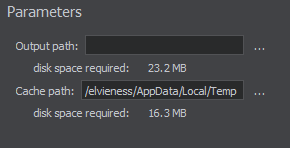
| Output path | Output path for generated terrain files. By default, a new folder in your project's data folder will be created. |
|---|---|
| Cache path | Path to cache files. |
Generating a Terrain#
The Landscape Tool stores the paths to all data sources as well as all generation parameters in an asset. So, after setting up all these parameters, you should save them by choosing File -> Save Asset and specifying the name and path for your asset.
Now you can generate the terrain by clicking the Generate button. In the Steps window, that appears, you can select what is to be generated.
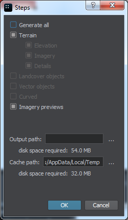
| Generate all | The whole terrain with detail masks, landcover objects and vector objects (spline, vector, and point) will be generated. This option is selected by default. |
|---|---|
| Terrain | Only terrain will be generated. Here you can select parts of terrain data used for generation (Elevation, Imagery, Details) |
| Imagery previews | The flag indicating if imagery previews are to be generated and placed at the corresponding location on the area displayed on the Preview panel. |
Also you can specify or change the output path for your terrain data and cache parameters.
If you have any unsaved changes, then after clicking OK in the Generation Steps window, you will see the window for saving the asset. Specify the name and the path for your asset and click Save.
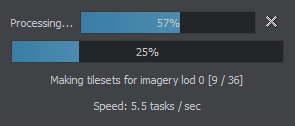
The generation status window will appear.

After successful generation process, the Landscape tool may offer your world settings optimizations. We recommend you to apply them, however, you can ignore.
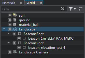
If you open the World Hierarchy window, you can see that the Landscape tool created the following instances:
- TerrainGlobal Landscape object.
- Beacons - NodeDummy objects generated for all elevation sources in the Play Area. These beacons can be used to quickly move to certain terrain location.
- The Landscape Camera camera object which is placed in the center point of the terrain with specified all the necessary parameters (far and near clipping planes).
