Built-In Physics Module
UNIGINE features a built-in physics module that allows you to simulate various types of physical interactions and phenomena.
Of course, it is just a simplified physics approximation with the impulse-based approach, so it isn’t suitable for high-precision scientific simulations. However, you still can handle a wide range of tasks, including:
- Collision detection (restricting interpenetration of solid bodies, preventing physical bodies from passing through walls, etc.)
- Simulation of perfectly elastic collisions (making colliding bodies bounce off each other like rubber balls)
- Simulation of various joints, motors, and springs
- Simulation of main physical phenomena: gravity, friction (static and sliding), buoyancy (for relatively calm water without big waves)
- Simulation of external forces (wind, force field)
- Procedural destruction of meshes
- Simulation of deformable cloth and ropes
- Ragdoll simulation
Remember that some cases cannot be solved using built-in physics. Here are some examples:
- High-precision physics simulation
- Flight dynamics simulation
- Fluid dynamics simulation
- Simulation of gravitational fields
- Simulation of inelastic collisions
- Digging into the ground
- Physical destruction of complex objects
Though some tasks involving a large number of objects can be solved using built-in physics, it may significantly reduce performance. In this case, you can consider alternative ways, such as bone-based animation, a code-based approach for changing transformations of objects and their behavior, and external physics engines.
Basic Entities#
Only Objects can have physical properties and interact with other objects and the environment.
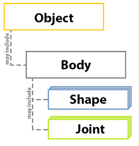
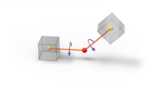
For these properties to be assigned, an object must have a physical Body — a physical approximation of the object, which determines the object’s behavior. Furthermore, the body must have at least one Collision Shape, which represents the volume of space occupied by the physical body. To connect bodies and restrict their movements relative to each other, Joints are used.
The picture below illustrates the interrelationships among these entities.
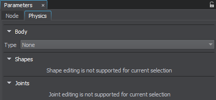
To assign and configure a body, shape, and joints, navigate to the Physics tab of the Parameters window.
Body#
As previously discussed, the physical body defines the object's behavior and represents a set of its physical parameters, including mass, density, velocity, and so on. In UNIGINE, there are different types of bodies, and each is used for modeling a specific type of object.
Rigid Body#
The most commonly used type of body that enables simulation of physical bodies according to rigid body dynamics. Rigid bodies cannot be deformed — their geometry does not change no matter what happens.
Ragdoll Body#
This type of body enables inverse kinematics and procedural animation for bone-animated characters. Essentially, this is a set of Rigid bodies, representing the character's bones connected by joints. These joints restrict the movement of the bones relative to each other, providing a realistic look.
To assign the Ragdoll body to the object, you should create a physical Ragdoll. You can automatically generate it based on the specified parameters or create it manually by preparing a Rigid body for each bone and then saving the bones hierarchy to a *.node file.
For proper automatic Ragdoll generation, the mesh should be in the Reference Pose (T-pose for human-like characters).
Fracture Body#
It enables real-time persuasive destruction of objects. A Fracture body is procedurally fractured into pieces when it collides with another body. Moreover, you can keep breaking these pieces until achieving the desired level of destruction.
The Fracture body (along with all the pieces it fractures into) is, in fact, a Rigid body that moves according to rigid body dynamics. When the body fractures, its mass is distributed among the pieces.
There are three patterns of fracturing: slicing, cracking, and shattering. You should choose the appropriate one depending on the mechanical properties of the material used to create the object.
The fracture patterns are specified in the code.
Rope Body#
It allows for the physical simulation of ropes, cables, and wires that can be torn. You can pin the ropes to the Rigid, Ragdoll, and Dummy bodies.
To attach a rope to another body, use the Particles joint.
Cloth Body#
It enables physical simulation of different types of textiles that can be torn. You can pin a Cloth body to the Rigid, Ragdoll, and Dummy bodies.
Polygon triangulation of the mesh, for which the Cloth body is generated, should be as illustrated! Otherwise, it may not stretch properly and evenly in all directions.
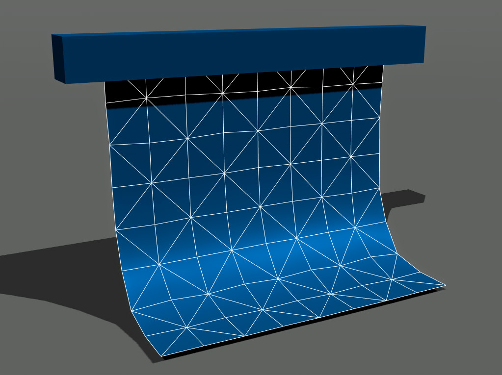
To pin a cloth to a body so it would hang like a cape or a curtain, use the Particles joint.
Water Body#
It enables the physical simulation of liquids of different densities and viscosities. It also allows creation of the buoyancy effect and wave dynamics.
A mesh to which the Water body is assigned should meet several requirements:
- The mesh should be flat and have a uniform grid.
- The mesh should be oriented strictly along the axes.
- The mesh should have the UV map.
Dummy Body#
It is a static body that does not move and has no physical properties. It can be used as a prop when connecting other bodies using joints.
For example, by using a Dummy body assigned to a Dummy object, you can fix a physical cloth (a Cloth body) so it can hang without any visible attachments. If the Dummy body does not have any Collision shape assigned, it will not fall or interact with other physical bodies.
Path Body#
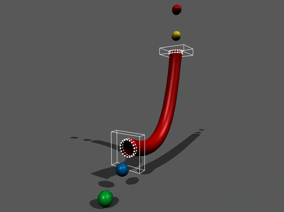
It is also a type of body without physical properties: it represents a spline along which an arbitrary rigid body can move. It can be used, for example, to create a physically simulated train moving along a rail track.
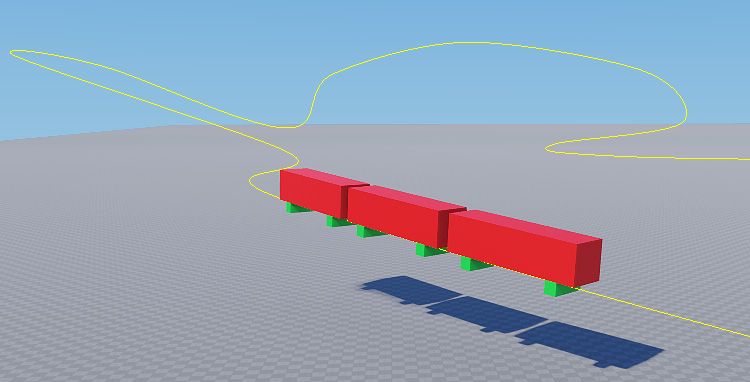
To connect a Rigid body to a Path body, use a Path joint.
Collision Shape#
A collision shape represents the volume of space a physical body occupies and is used to detect collisions. The collision shape is invisible and doesn’t have to be the same as the object’s mesh. In fact, a rough approximation — like a sphere, capsule, cylinder, or box — is often more efficient since it consumes fewer resources.
The physical body can have one or more collision shapes.
Objects with shapes fall under gravity, bounce off static surfaces, or slide along them. How they slide and bounce depends on restitution and friction coefficients.
When a body does not have a single shape assigned, it behaves as a Dummy body. It can be connected to other bodies using joints but does not collide with them and is immune to gravity.

There are two basic types of collision shapes:
- Simple primitives — a sphere, capsule, cylinder, box. They are very fast and memory efficient. It is a good idea to use them whenever you can. In addition, spheres and capsules use continuous collision detection, but we will consider it later.
- Complex collision shapes — composed of polygons or several simple shapes. They are slower and need more memory. They also include a convex hull and a set of auto-generated convex hulls.
The simple primitives, like spheres and boxes, make collision calculations easier while keeping performance high and accuracy acceptable. On the other hand, convex hulls are more precise but don't use continuous collision detection. So, they are not suitable for fast-moving objects.
A shape doesn't have to duplicate the mesh it approximates. Try to use simple primitives whenever possible — they are fast and usually give correct results.
And keep the number of shapes as low as possible: fewer calculations - higher performance!
The collision shape can't exist without a physical body. It also doesn't have a position in world coordinates. It must be assigned to a body and positioned relative to it. There are several shape types:
Sphere#
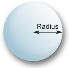
A sphere is the simplest and the fastest shape, as it has only one parameter — a radius. For this shape type, continuous collision detection is available. So, you can be sure it will not go through other objects, even if it moves at high speed (we will learn about that later).
Using the spherical shape for any arbitrary mesh ensures collision detection.

To make the shape fit your object, you can adjust the sphere Radius:
Capsule#
A capsule is another fast collision shape with continuous collision detection available. You can use capsule shapes to approximate elongated objects like pillars or even human-like characters. These shapes help the characters go up and down the stairs smoothly, without stumbling at each step, as long as the steps are not too high. Capsule shapes also ensure that the character's arms or legs do not get stuck unexpectedly.
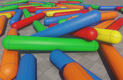
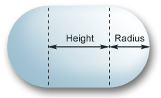
To make the shape fit your object, you can adjust the capsule Radius and Height:
Cylinder#
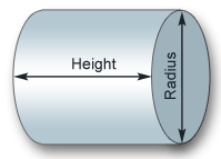
A cylinder can be used to approximate elongated shapes with flat ends (for example, shafts, or pylons).

To make the shape fit your object, you can adjust the cylinder Radius and Height:
Box#
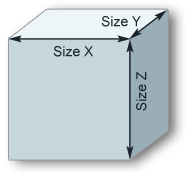
A box is a cuboid shape that can approximate the volume of various objects: walls, doors, stairs, parts of mechanisms, car bodies, and many other things. You can choose the size of a box shape in each dimension arbitrarily.

To make the shape fit your object, you can adjust the box size (Size X, Size Y, Size Z):
Convex Hull#
A convex hull is the slowest of all shapes. Usually, it is used for objects with complex geometry. This shape is the smallest one that can enclose vertices of the approximated mesh. At that, it includes holes and cavities of the mesh in the shape volume.
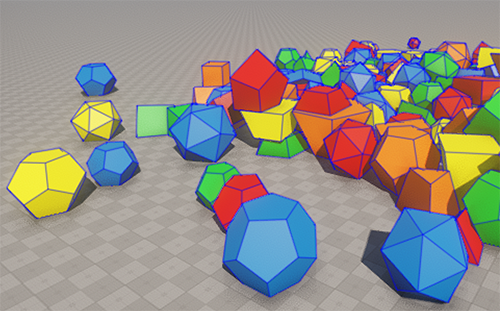
To generate a convex hull, specify the Approximation Error value that allows reducing the number of vertices of the created shape. Note that simple and rough convex hulls with a small number of vertices are processed faster, so we recommend keeping the number of vertices as low as possible.
The higher the error value, the fewer vertices in the generated shape, but the more mesh details are skipped.

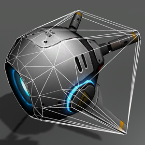
Approximation error = 0
|
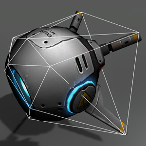
Approximation error = 0.1
|
Autogenerated#
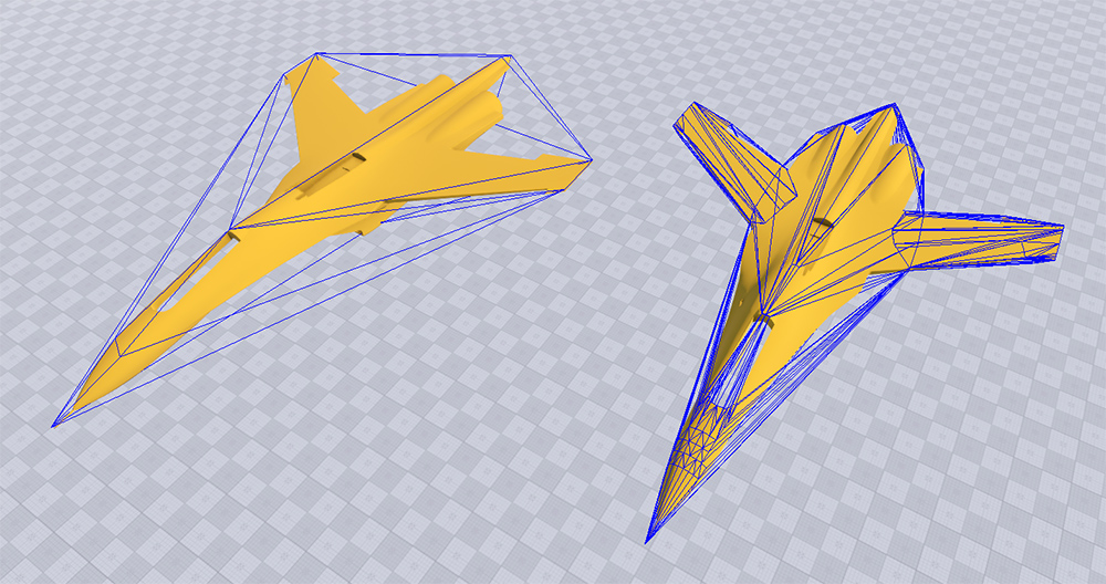
An autogenerated shape is a set of convex hulls that can approximate a complex concave object and exclude cavities from its volume.
In the picture below, you can see a complex concave object. On the left, it's approximated with a single convex hull. And on the right — with an autogenerated set of convex hulls.
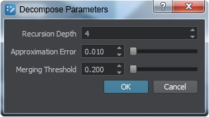
When generating this type of shape, you should specify the following beside the Approximation Error value:
- Recursion Depth that sets the degree of mesh decomposition.
- Merging Threshold that determines the volume threshold for merging convex shapes after decomposition.
The values you specify affect how many shapes are generated and how well they fit the object.
Joint#
In the real world, we often see connected objects, such as a door fixed in a doorway, a helicopter propeller mounted on its fuselage, elements of a robotic arm, or even the bones forming a skeleton. Joints help us make these connections. They allow us to create complex objects consisting of several interconnected parts, each with a certain degree of freedom of movement relative to each other.
In simple terms, a joint connects two bodies and restricts their movement relative to each other. When you apply too much force to the joint, it can break.
There are several types of joints:
- Fixed
- Hinge
- Ball
- Prismatic
- Cylindrical
- Suspension
- Wheel
- Particles
- Path
When you use joints, ensuring mass balance is crucial. Avoid connecting too heavy bodies to light ones. Remember, physics simulation uses approximate calculations, so if two connected bodies are very different in mass, accumulation of errors and precision issues lead to unstable results.
Thus, when making a car model, do not set the mass of the car body equal to 2000 kg and the wheels — to 10 kg. It might be better to use 5 kg for the body and 1 kg for each wheel to provide realistic behavior.
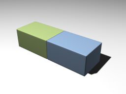
Fixed Joint#
A fixed joint connects two bodies in a manner that strictly preserves their positions relative to each other. An example of such a connection in real life is welding or gluing two objects together.
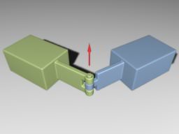
Hinge Joint#
A hinge joint allows the connected bodies to rotate along the joint's axis at the anchor point. The joint has an angular motor attached. Hinge joints are used for doors and the arms and legs of characters.
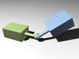
Ball Joint#
A ball joint provides a point around which the connected objects can rotate. It is similar to the hip joint. You can limit rotation by using the corresponding parameters.
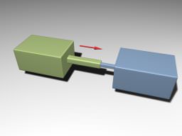
Cylindrical and Prismatic Joints#
These joints are similar — they both allow movement along the joint axis, which can be used for piston simulation. The cylindrical joint has an additional degree of freedom — rotation around the joint axis.
 |
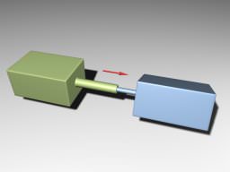 |
| Prismatic Joint | Cylindrical Joint |
Hinge, Ball, Cylindrical, and Prismatic joints are used to create connections in mechanisms with the specific restrictions of the movement of bodies relative to each other. In addition to these main types of joints, UNIGINE also provides auxiliary ones.
Wheel Joint and Suspension Joint#
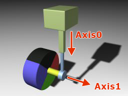
These joints are intended to simulate vehicles and the interaction of vehicle wheels with the ground.
They both simulate wheel suspension and have angular motors attached. The main difference is that the suspension joint operates with the physical shape of the wheel, which serves for accurate collision detection. While the wheel joint handles a virtual wheel and checks for intersections with the ground via ray-casting. This approach is faster and provides an acceptable result on smooth terrain. In case of a stepped ground surface, it is better to use the suspension joint.
Particles Joint#
A Particles joint allows pinning a Cloth or Rope body to a Rigid, Ragdoll, or Dummy body. For example, you can use it to hang a flag or attach a cloth to a character.

Path Joint#
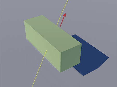
A Path joint is used to attach a Rigid body to a Path body and to make the Rigid body move along this path.
Physical Effects#
Various physical effects can affect physical objects — wind, force fields, Archimedes' force when a body is immersed in a fluid. In UNIGINE, we use the Physical objects to represent these effects.
You can add a physical effect to a scene via UnigineEditor. Just click Create → Physics in the Menu Bar and choose the required object. You can adjust its settings in the corresponding tab of the Parameters window.
Also UNIGINE SDK Browser provides a set of samples demonstrating the usage of the Physical objects. You can easily find them in the Samples → UnigineScript → Force Fields section and run in UnigineEditor to see how they work.
Physical Wind#
Physical Wind is a cuboid-shaped object simulating wind blowing within its volume.
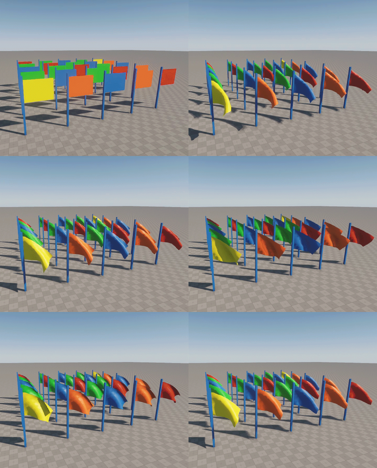
The wind only affects objects placed inside the Physical Wind box and having physical bodies assigned.
The wind differently affects objects with different physical properties. So, besides changing the Physical Wind parameters, you should adjust the parameters of the physical body.
For example, if you place an object with the Cloth body inside the Physical Wind volume, the way it "waves in the wind" will vary depending on the Cloth body mass, rigidity, and other parameters.
When you set up the wind, you can change the size of the volume in which the wind blows, specify the wind velocity, attenuation threshold, and damping of the linear and angular velocities of the objects when they get inside the wind volume.
You can also choose which physical bodies are affected by the wind. For example, you can make only one flag flutter in the wind while the others stay still. For this purpose, there is the Physical mask — it must match the Physical mask of the physical body affected by the wind.
Force Fields#
The Physical Force and Physical Noise are objects for creating force fields.
The Physical Force is a spherical object with a force that is applied to its center and attenuates within a specified radius. Objects within the sphere can pull up to or away from the center and rotate around it.
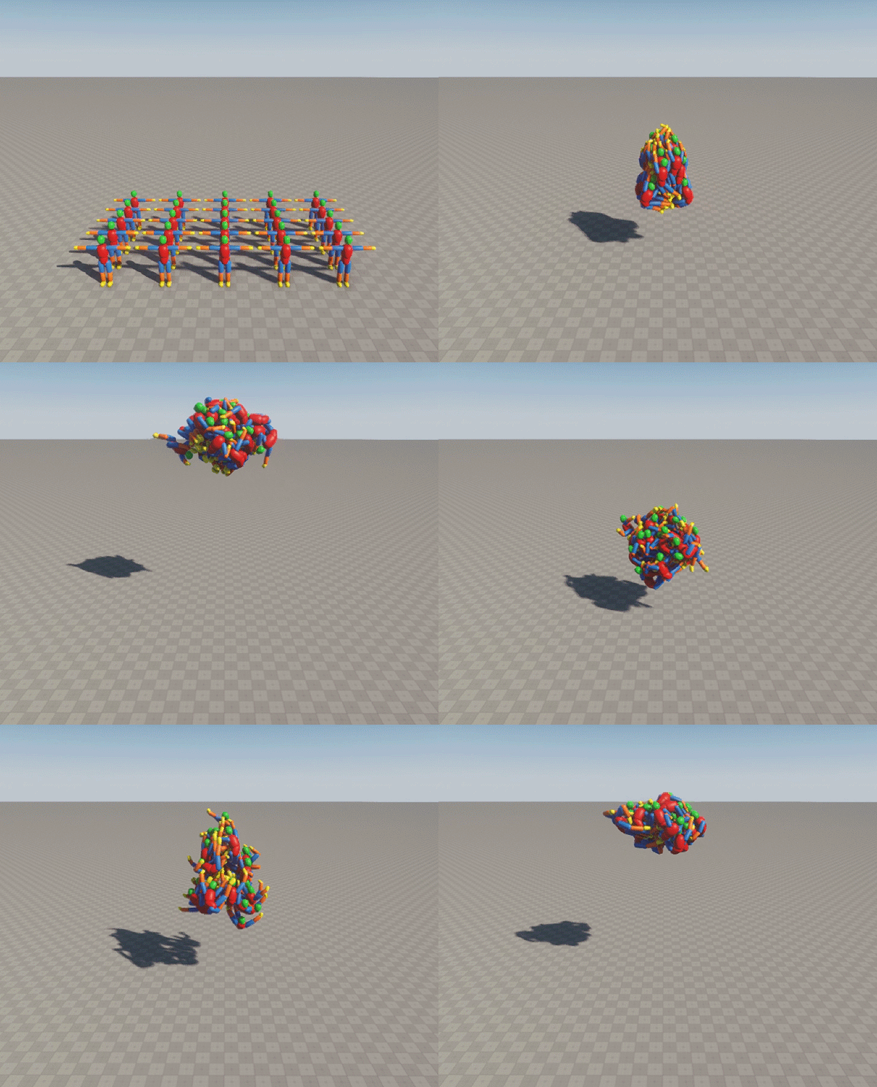
You can control the attenuation of the force affecting the object that moves away from the force center. In addition, you can adjust the intensity of the attraction and rotation forces that define the speed and direction of rotation.
The Physical Noise is a cuboid-shaped area that adds a distribution flow based on a volumetric noise texture. This effect simulates a force field that affects particles and physical bodies.
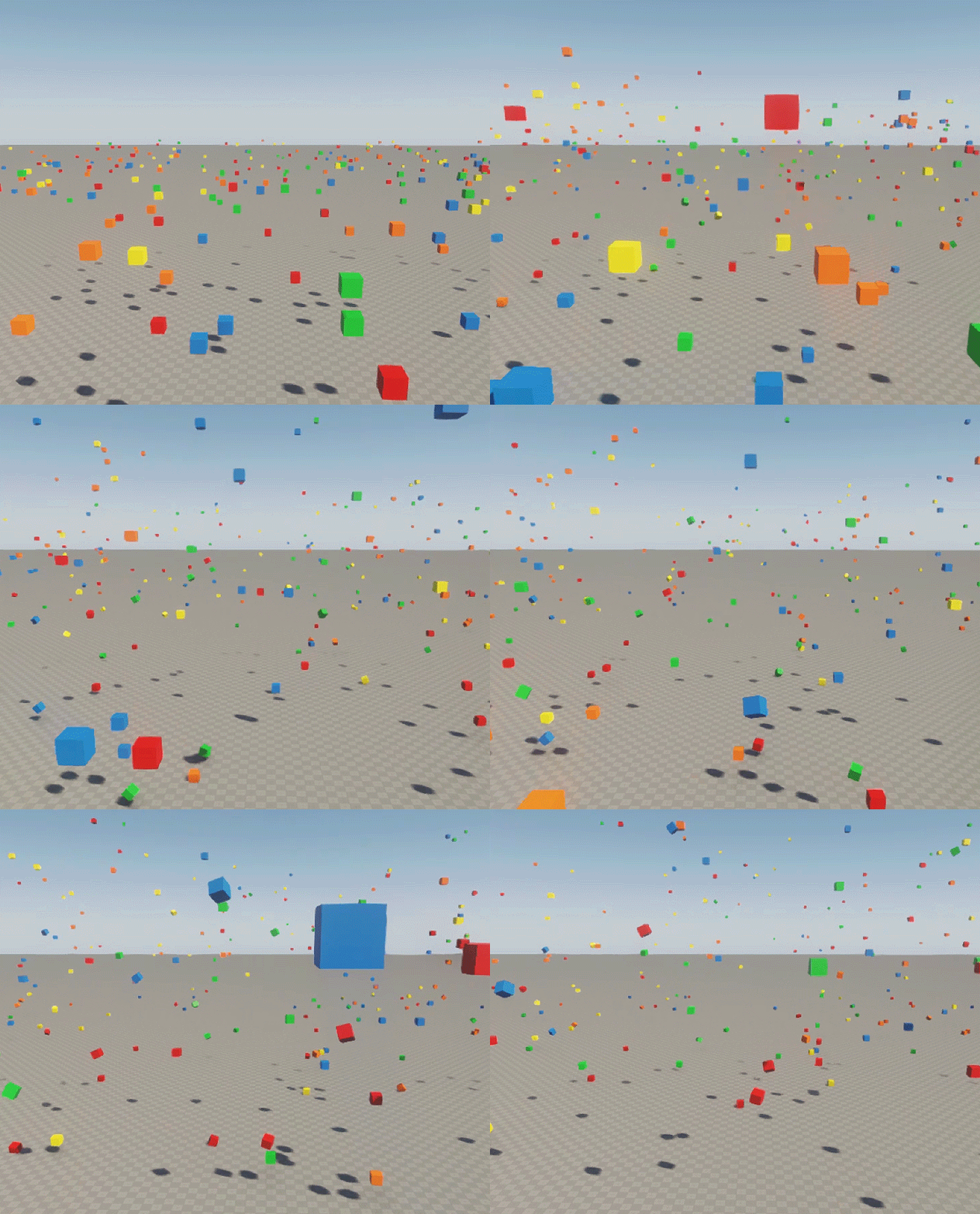
- Physical Noise affects only the Cloth, Rope, and Rigid bodies. At that, the Rigid body must have a collision shape assigned.
- Physical Noise will affect particles only if their physical mass is non-zero. You can set this in the settings of the Particles object.
The direction of the force affecting particles and physical bodies within the Physical Noise volume is stored in the Noise texture — a 3D texture, where each texel stores the force direction.
To be sure that the force at the current point affects the physical body entering the Physical Noise volume according to the Noise texture, you need to provide the texture generation and sampling parameters for the Noise texture, along with the Force multiplier.
Floating Bodies#
The Physical Water is a cuboid-shaped object that allows the simulation of water interaction effects within its volume.
This effect is helpful for the simulation of physical interactions of bodies with the Water Global, as this water object doesn't support the Water body because of large-scale computations. You can use the Physical Water to simulate the floating physical bodies within a certain area.
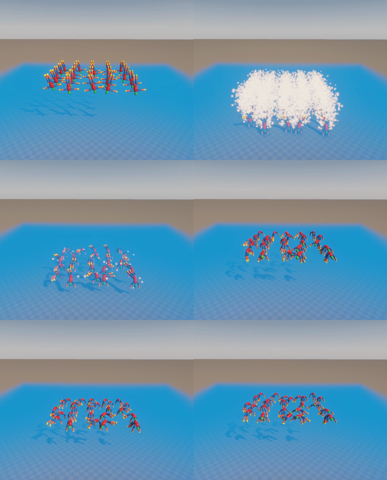
To add the Physical Water to your scene, select Create → Water → Physical Water in the Menu Bar of UnigineEditor.
- The Physical Water can only interact with the Cloth and Rigid bodies. At that, the Rigid body must have a collision shape assigned.
- Physical Water does not simulate waves.
The bodies with different physical properties act differently in the Physical Water. So, besides changing the Physical Water parameters, you should adjust the parameters of the physical body as well.
You can also create additional water effects with Physical Water — for example, foam on the water surface or water splashes — by generating particles in the contacts between the Rigid bodies and Physical Water. Add your Particles object as a child to Physical Water to implement the required effect.
Physical Triggers#
The Physical Trigger is an effect that fires callbacks when physical objects get inside or outside its volume.
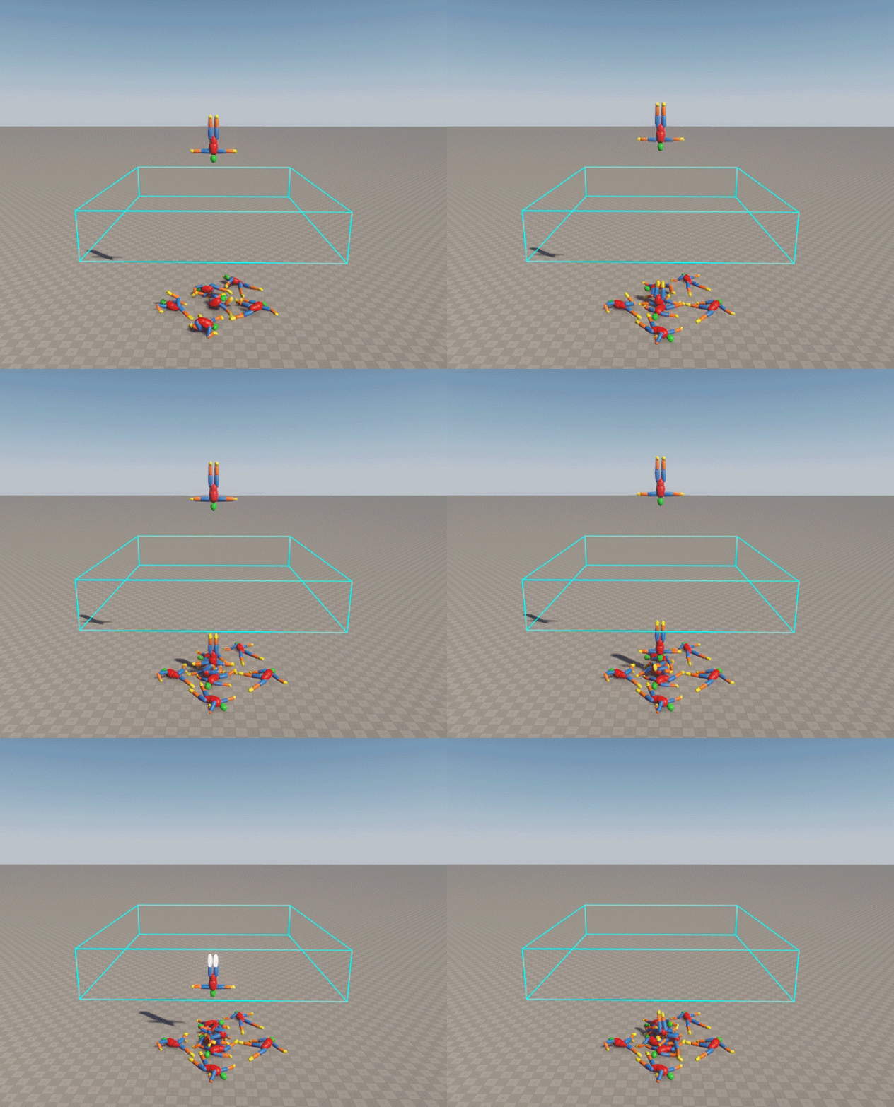
The trigger can be of the box, sphere, capsule, or cylinder shape.
To add the Physical Trigger to your scene, select Create → Logic → Physical Trigger in the Menu Bar of UnigineEditor.
To be detected by the trigger, a physical object must have both:
- A physical body with the Physical mask that matches the Physical mask of the trigger.
- A shape with the Collision mask that matches the Collision mask of the trigger.
You can obtain the physical bodies participating in the contact with the Physical Trigger and their collision shapes via API. In addition, you can get values such as the depth of penetration of the body into the trigger, the coordinates of the contact point and the normal to it.
To define actions to be performed when the body enters and leaves the trigger, do the following:
- In UnigineEditor, create a C# component and open it.
- Implement a callback function that receives a Body as the first argument.
- In the Init() function, get the instance of the Physical Trigger and call the addEnterCallback() or addLeaveCallback() method for it with the implemented callback function name as an argument.
- Assign the implemented component to the Physical Trigger node in UngineEditor.
// callback functions
void EnterCallback(Body body){...}
void LeaveCallback(Body body){...}

PhysicalTrigger physicalTrigger;

private void Init()
{
    // cast the node to the PhysicalTrigger type
    physicalTrigger = node as PhysicalTrigger;

    if (physicalTrigger != null)
    {
       // function called when the body enters the trigger volume
       physicalTrigger.AddEnterCallback(EnterCallback);

       // function called when the body leaves the trigger volume
       physicalTrigger.AddLeaveCallback(LeaveCallback);
    }
}
Simulation of Physics#
In physics simulation, physics calculations are in the multi-threaded mode — some operations are performed in parallel. Physics is simulated with its own fixed frame rate, which doesn’t depend on the rendering frame rate. You can also synchronize the Engine frame rate with the physics one.
If physics takes more than the assigned budget, further calculations are delayed. These calculations shall be performed during the subsequent rendering frames, making the physics simulation look like in the slow-motion mode. The default budget is 50ms, but you can increase it if necessary.
During each tick, several calculation iterations can be performed. This includes the full cycle of physics simulation:
- Updating physics
- Collision detection
- Solving joints
- Collision response
- Physics synchronization
There are two update modes available for physics simulation (each of them has its advantages and use cases):
- Before Rendering — the physics update (along with the spatial tree update and user callbacks) is executed in the Main thread just before rendering is performed (render). The number of physics ticks executed before the rendering frame here is defined by the physics and Engine frame rates. This update mode is the most clear and straightforward (everything is executed safely in a strictly determined order) with no frame lag (results of physics calculations are applied in the current frame). But, on the other hand, this mode is the slowest as there are no asynchronous parallel calculations (everything is in the Main thread). Use this mode if the time lag is unacceptable for your application (you need all physics calculations to be applied in the current frame) and you want maximum simplicity and strictly determined order of execution for user code (physicsUpdate and physics callbacks).
- Async Rendering — physics update is performed asynchronously to rendering. In the case of several physics ticks per one rendering frame (when the Engine frame rate is lower or catching up is performed), only the first one is executed in parallel. Then the physics module waits for the completion of the rendering process, returns to the Main thread, and executes the rest of the physics ticks. There is a frame lag (results of physics calculations are applied in the next frame) and some ambiguity regarding the time when the user code (physicsUpdate and physics callbacks) is to be executed in case of several physics ticks per one rendering frame (some part is executed before rendering while the other just after it). This mode is the fastest one and is used by default.
As the Engine has a variable framerate while the physics framerate is fixed, the execution of physics calculations always adapts to the current situation.
If the Engine framerate drops below the physics frame rate (which is a rare case), some physics frames do not have enough time for execution and become missing. The physics module keeps such missed frames in memory for a certain period (called Missed Frame Lifetime) and tries to execute them when the situation gets better (Engine FPS grows) or when the CPU is idle while waiting for the GPU to complete rendering (if there is enough time). This approach is called catching up and helps to avoid the slow-motion effect occurring when physics frames are dropped off. In case of insufficient hardware capabilities, missed frames are removed from the buffer as their lifetime expires, and they become lost forever.
The actual time of physics calculations can go beyond the current budget as the ones performed while waiting for the GPU are not taken into account. So, the budget is not strict in this respect and can be exceeded if the CPU is idle.
Physics also has the Deterministic mode that ensures that all contacts are solved in the predefined order and visualization of physics in the world is repetitive (on one computer).
At that, the Deterministic mode is unavailable in case there are missed frames. This mode may eat up to 10-20% of the frame rate, and it also depends on the scene a lot.
Global Physics Settings#
As you already know, every virtual world has a set of global settings. The same goes for physics. You can find the physics settings in the Runtime → World → Physics section of the Settings window.
These settings serve for optimization (we will talk about this later) and additional adjustment of physical interactions in the world. For example, you can use them to simulate a planet with its gravity.
The current physics settings can be saved to a separate *.physics file for later re-use.
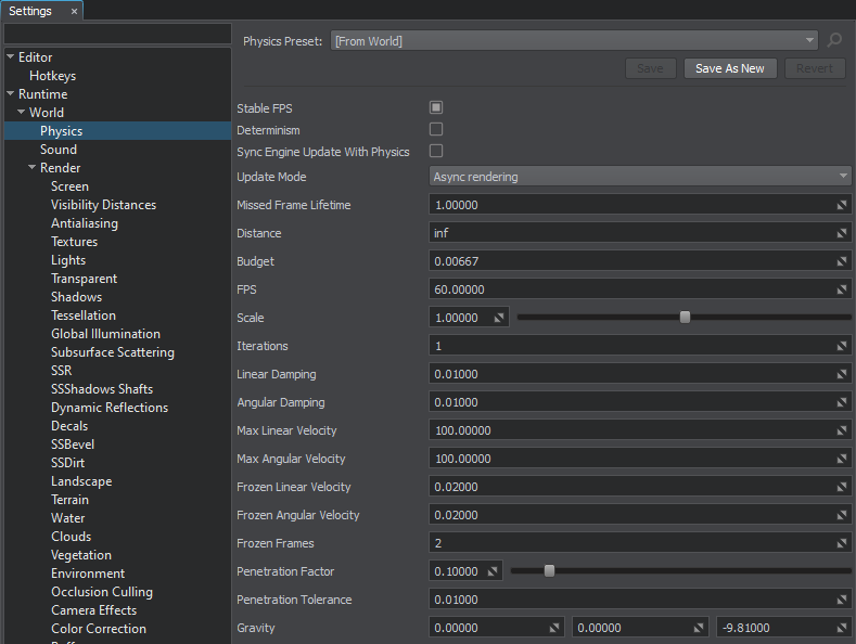
Using these settings, you can set the gravity, physics frame rate, and distance from the camera at which physics is simulated. Also, you can define the optimal number of iterations for physics during one physics tick and find the appropriate physics simulation time budget.
In addition, you can control the physics calculation time, speed up or slow down the simulation time, adjust the linear and angular velocity of physical objects, and define their behavior in collisions.