World Structure and Built-In Objects
A UNIGINE-based virtual world is a 3D scene that contains a set of different scene graph nodes (e.g. static meshes, lights, cameras, etc.) placed into specified positions, and global settings (rendering, physics, etc.) applied to the whole scene.
In terms of UNIGINE, all objects added to the scene are called nodes. Nodes can be of different types, determining their visual representation and behavior. All nodes are arranged into a hierarchy: there are parent and child nodes; one node can have several child nodes. A scene graph in UNIGINE is a multi-root tree (hierarchy) of nodes. Each world is represented by an XML file with the *.world extension.
To edit your existing worlds and create new ones, use UnigineEditor. You can create and use as many worlds as you need.
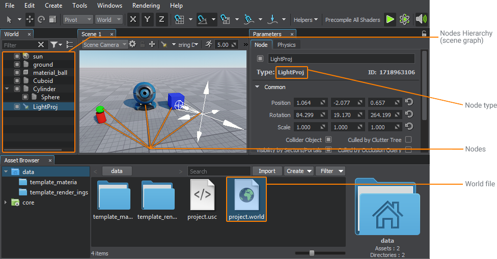
There is a rich set of built-in node types with various functions. Though the set covers almost all of required cases, it can be manually extended by the user. You can also extend basic functionality of any node by adding components to it.
Coordinate system. Local and global coordinates#
Each node has a transformation matrix that defines its position, rotation and scale in the virtual world.
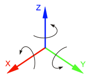
The three-dimensional space in UNIGINE is represented by the right-handed Cartesian coordinate system where the X and Y axes form a horizontal plane, and the Z axis points upwards. The Y axis in UNIGINE always points forward, but in third-party editors the forward axis direction may be different. Take this into account when exporting models.
A positive rotation angle specifies counterclockwise rotation. This corresponds to the right-hand rule: if you place your right thumb along the axis, the direction of the other fingers will show the direction of rotation.
The position of the first-level nodes (parent nodes) is set in global coordinates. The position of child nodes is set in local coordinates relative to the parent node (unless other conditions have been set). Due to this, any transformation (moving, rotation, resizing) of one parent node will result in transformation of all children: we can move just one node by specifying its coordinates in global space, and the children nodes location will be calculated automatically.
The basis of the global coordinate system is located in the origin of the virtual world and is set automatically. In case of the local coordinate system, the pivot point of the parent node is taken as the basis.
Parameters of all nodes in the world are usually stored in a file with the *.world extension, but can also be stored in separate XML files with the *.node extension. These files can be referenced from the *.world file via Node Reference — a specific node designed for various purposes (object templates, dividing the world hierarchy into segments).
Basic objects#
Let's review main node types available in UNIGINE. They are divided into groups depending on their purpose. There are nodes that have a visual representation: objects, effects, and decals. They have surfaces that define their geometry (polygonal mesh). The other types of nodes (light sources, physical effects, cameras, etc.) are invisible.
Nodes#
This group includes such types as Node Reference, Dummy Node, Layer Node, and Trigger Node. Let's review them in detail.
Node Reference#
This type of node refers to a *.node file on the disk, which contains a pre-fabricated node (or a hierarchy of nodes) with links to all materials, properties, physical bodies, and components that are required for its rendering and behavior. Node Reference is used for placing of multiple identical objects (instancing — we'll talk about that in the next chapter in more detail), which point to one and the same *.node asset. Editing and saving only one Node Reference will update all placed copies.
Dummy Node#
This is a zero-sized node that has no visual representation. It is used to organize other nodes into a hierarchy and control them as a group by transforming or enabling/disabling the parent Dummy Node. This node can have logic assigned via a component.
Layer Node#
This node is also invisible and used as a container for editing other nodes. Layer Node allows saving all its child nodes into a separate *.node file, enabling you to split the world into several logical parts and save each of them separately. This approach facilitates collaborative work on one project by eliminating conflicts arising from simultaneous editing of this world by several people (changes in child Layer Nodes do not affect the *.world file).
Unlike Node Reference, it is impossible that multiple Layer Nodes refer to the same *.node file. This will lead to conflicts when saving changes.
Trigger Node#
This is a zero-sized node that has no visual representation. It fires callbacks on transforming and enabling/disabling its parent node.
Objects#
Objects are a virtual representation of entities or objects from the real world. They are used to build the virtual world: you can create sky, terrain, water, buildings, characters, any objects using the corresponding types of objects.
Dummy Object#
This is an empty invisible object similar to Dummy Node. The only difference is that it can have a physical body assigned and therefore is used as an invisible object with physical properties. For example, you can use it to fix the fabric in a specific position.
Mesh Objects (Static, Skinned, and Dynamic)#
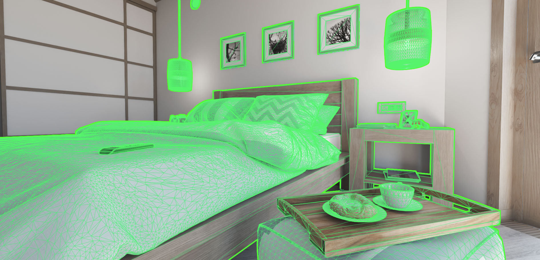
Static Mesh is an object consisting of polygons that define its geometry. This geometry is stored in the *.mesh file and is always unchanged. Usually Static Mesh is used to create static geometry, such as buildings or furniture. The geometry of such objects is created in third-party 3D editors and then imported into the engine. In addition to Static Mesh, there are two other similar objects used in specific cases:
- Dynamic Mesh is an object the geometry of which can be modified procedurally. As a rule, such modification is required to change the object shape as a result of some external impact (clash, explosion) or to create dynamically changing surfaces (fabric, wire, liquid, etc.).
-
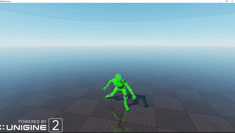
Skinned Mesh is an object used to create characters with skeletal animation or animation based on a set of distorted versions of an object (morph targets or blend shapes). In addition to geometry, it contains animation data.
UNIGINE also uses composite objects based on Static Mesh for optimization purposes:
-
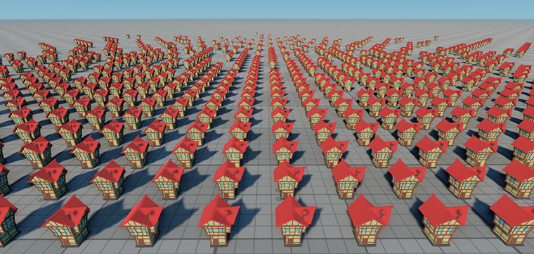
Mesh Cluster is an object that can contain a great number of identical meshes placed around the scene as you see fit. Mesh Cluster manages these meshes as one object, but their position and rotation can be changed manually. This object is usually used to place multiple identical objects, for example, houses in a neighborhood. Identical mesh objects can be baked to Mesh Cluster manually or in semi-automatic mode.
-
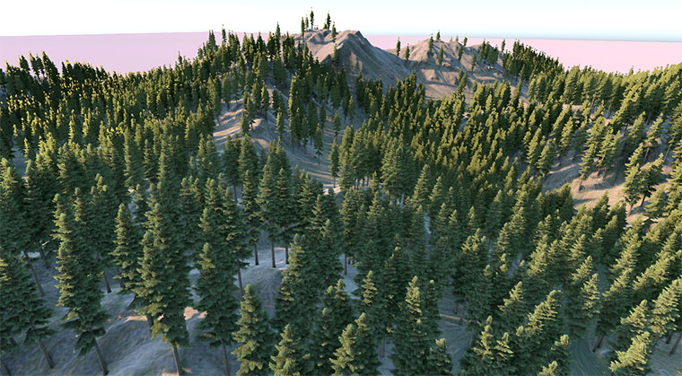
Mesh Clutter is an object that containing identical meshes. However in this case meshes are positioned randomly and cannot be managed manually. Mesh Clutter is used to fill the scene with vegetation (for example, to create a forest) or place identical objects (leaves, branches, garbage). Areas where meshes can be placed are defined by specific masks.
Landscape Terrain#
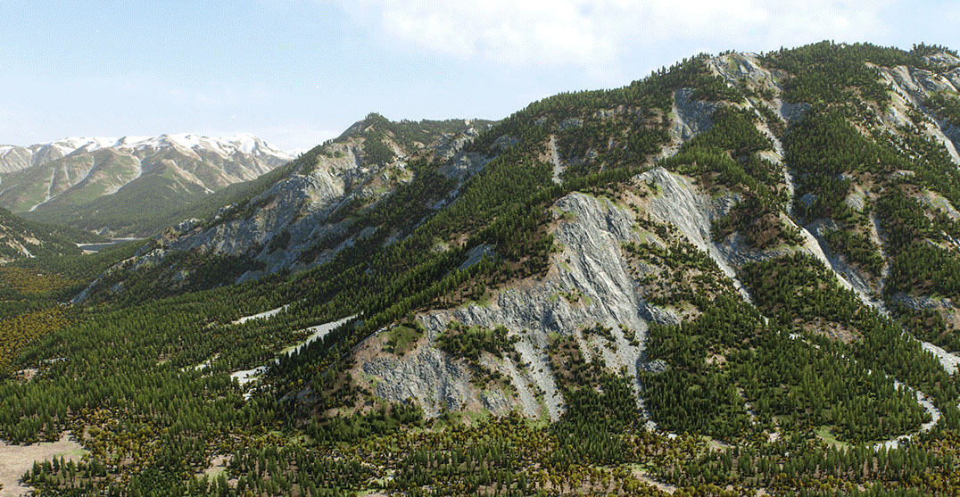
UNIGINE has Landscape Terrain, which is used to create a virtually infinite arbitrary landscape with high level of detail, optimized performance, and flexible settings. It supports collaborative editing and the ability to modify the surface in real time (creating craters, explosion funnels, and trenches). The Landscape Terrain object consists of individual layers (Landscape Layer Map), each storing the data used for rendering (elevation, imagery, and masks). These layers are blended to create a realistic landscape. You can draw a landscape from scratch in the Editor or use data generated in a third-party application.
You can also use the Terrain Global object to create a landscape — it has specific features and is mainly used for flight simulators. We are not going to review this object in the course.
Water#
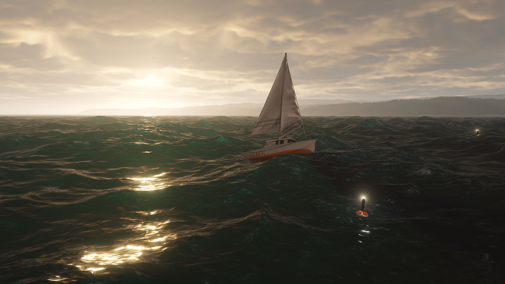
To create realistic water (with waves, ripples and foam, reflection and refraction effects) and various liquids, UNIGINE provides two objects:
- Global Water is an infinite mesh with automatic tessellation used to create the global ocean. This object has an underwater mode, and the water level is the same everywhere. You can create realistic waves on the surface by setting the Beauforts mode or using the Layers mode. The object does not interact with physical objects as this would require a large amount of calculations.
- Water Mesh is used for finite basins (pools, ponds, lakes, etc.), as well as for modeling any liquids in a confined basin of arbitrary shape. It can be used to create a mountain lake or a stream of water with an altitude difference above sea level. This object supports interaction with physical bodies (buoyancy simulation) but has no underwater mode. You can create ripples and waves on the surface using the Normal map or a combination of four directional geometric waves.
Sky#
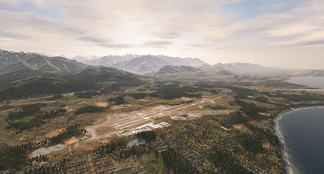
This object is used for simplified simulation of the planet's atmosphere. It is modelled as an upper hemisphere of the specified color with dynamic clouds generated using a special texture.
Cloud Layer#
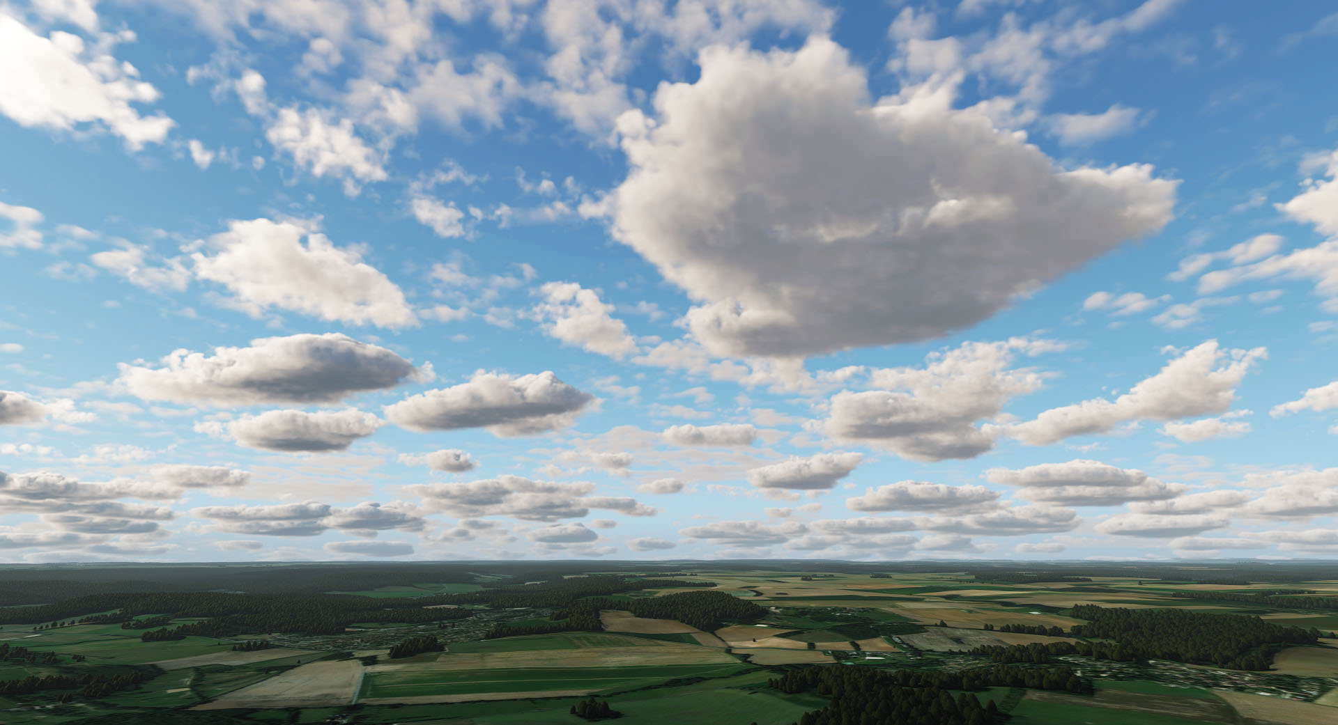
This object allows generating layers of volumetric clouds that drift across the sky, with realistic lighting, shadow casting, and interactivity.
It supports the 10 basic types of clouds that exist in nature (cumulus, cirrus, etc.), which are available as customizable presets, and you can simultaneously add several different layers at different heights. Support for the Earth's curvature is also available to make the cloudy sky conform to the planet's shape.
Grass#
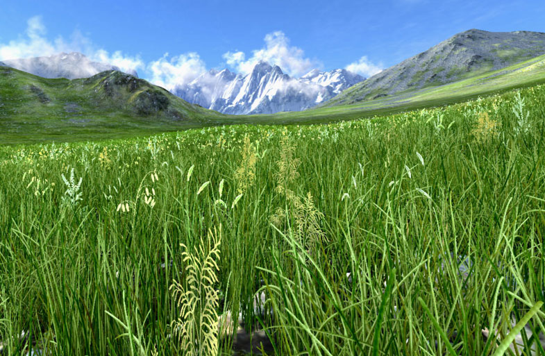
This object is used to create animated vegetation, including grass. Its appearance is determined mainly by two textures: the Diffuse texture, which defines variations of each type of vegetation, and the Mask texture, which defines the areas of growing and density.
Vegetation diversity is also achieved through a probability factor that affects height, color, slope, rotation, and other parameters.
Billboards#
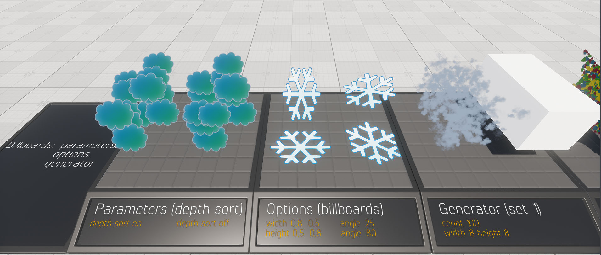
Billboard is a rectangular flat object that always faces the camera. The Billboards object consists of a number of such billboard elements. It is used instead of fully functional objects that are barely seen from far off and slightly change their position when the camera moves around them (such as stars, clouds, or trees at a distance). Using Billboards helps to speed up rendering.
Depending on its purpose, a Billboards object can be of either of three types (Base, Impostor, or Cloud) and is assigned a corresponding material. Materials differ in a set of parameters and are displayed in different ways.
Effects#
UNIGINE has several types of nodes that provide visual effects:
- Particle system is a complex object consisting of an emitter, particles, and additional physical forces affecting the particles. It is used to create fire, smoke, fireworks, fountains, snow, rain, etc. We will review this node type in more detail later.
-
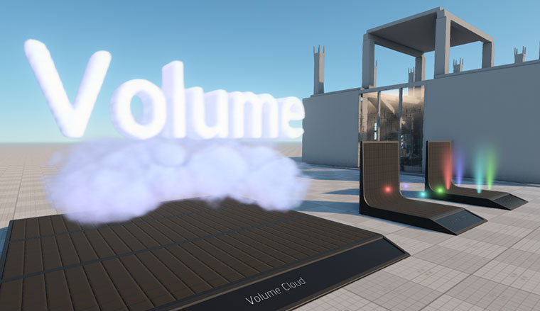
Volumetric objects are used to create volumetric effects (fog, clouds, sun rays, etc.):
- Volume Box creates a volumetric effect of rectangular shape: fog, clouds, rays of light from the sun.
- Volume Sphere creates a spherical or ellipsoidal volumetric effect such as fog, haze, or glow around point light sources (candles, lamps, etc.).
- Volume Omni creates a visible volume of light emitted from a flat surface (e.g. flat wall and ceiling lamps).
- Volume Projected creates light rays from directional light sources (car headlights, spotlights).
-
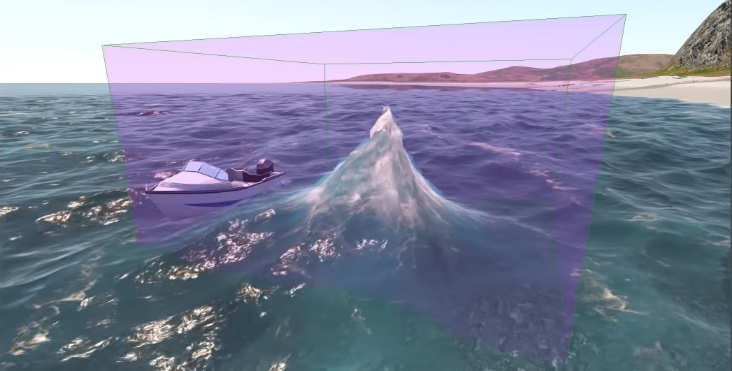
Fields – box or ellipsoid-shaped objects that affect certain areas of grass, water, or clouds within their volume in a specific way:
- Field Spacer cuts out areas of grass and water geometry.
- Field Animation animates grass and water geometry.
- Field Height defines areas of Global Water where the water level should change due to external effects (e.g. to create a wake or water disturbance near certain objects).
- Field Shoreline defines the areas of Global Water where shoreline swash zone should be located.
- Field Weather defines the location of cloud areas within the Cloud Layer. It helps to create a local storm, or clouds of the desired shape.
-
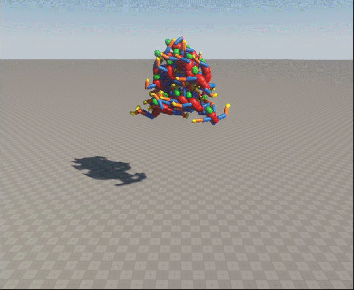
Physicals – objects inside of which there is an invisible force field affecting other objects. These objects allow simulating wind, force fields, floating. We will review them later in detail.
Decals#
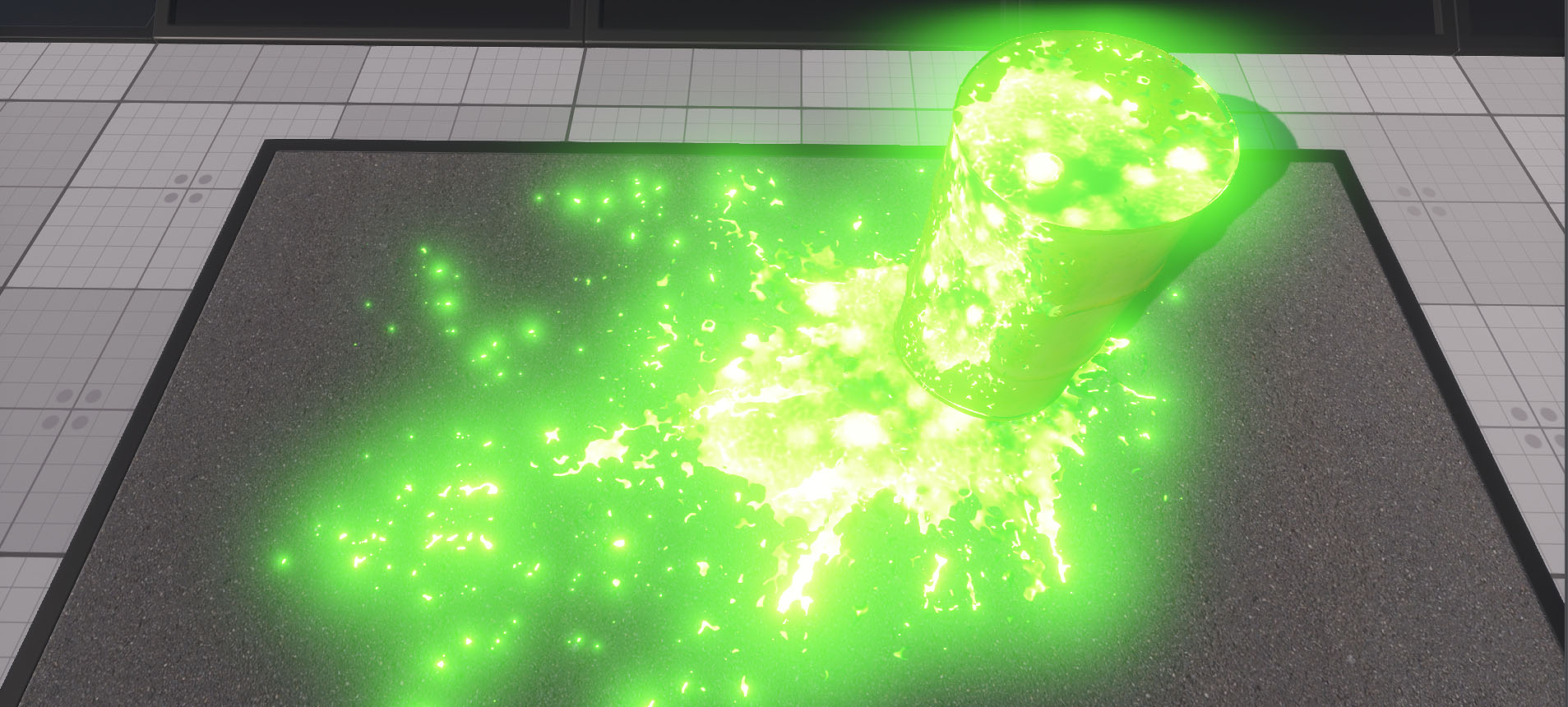
Decal is a material projection on the surface. Decals allow adding details — they help imitating holes, stains, traces, puddles, etc. Decals can also be projected onto the water surface and used to create holes in the landscape.
There are three types of decals in UNIGINE:
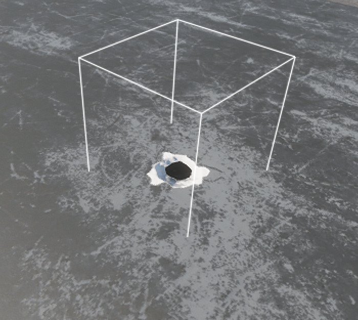
- Orthographic Decal is a decal projected onto a surface using orthogonal projection. Its size is independent of the distance to the surface on which it is projected. This decal follows the shape of any surface, so it looks realistic.
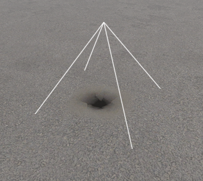
- Projected Decal is a decal projected onto a surface using perspective projection. The decal size increases as the distance to the surface increases. Projected Decal forms a projection pyramid, the size of which can be adjusted using the settings.
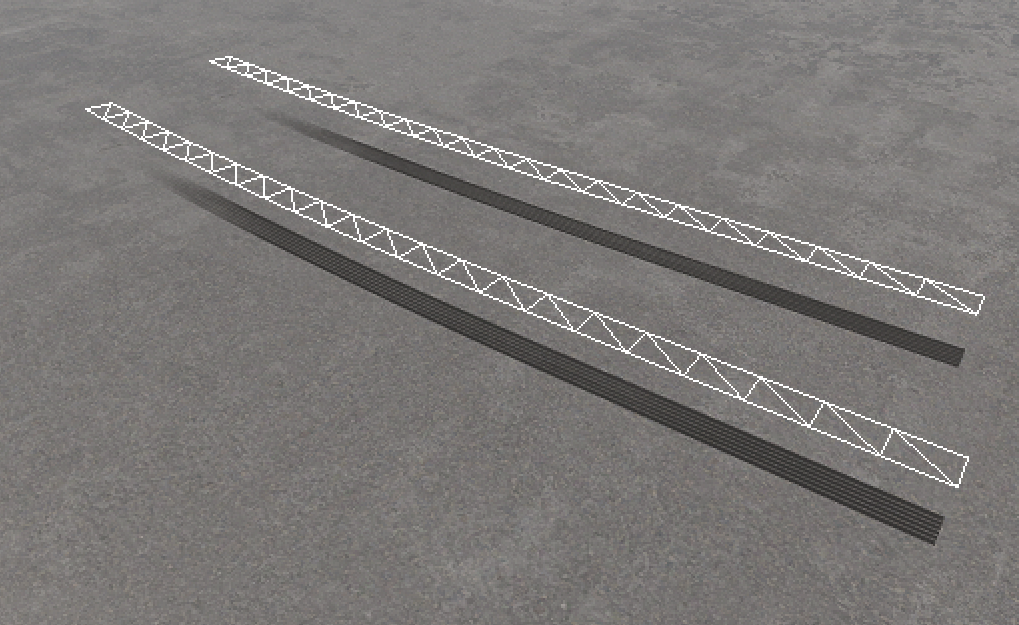
- Mesh Decal is a decal that projects arbitrary geometry onto the surface using orthogonal projection. This type of decal is suitable for creating large objects with complex shapes (e.g. an entire airfield).
| Orthographic Decal | Projected Decal |
|---|---|
|
|
| Mesh Decal | |
|
|
World Nodes#
Nodes from this group are invisible and are used to control the virtual world:
- World Trigger activates certain events when any objects enter or leave its bounds.
- World Clutter manages a large number of Node Reference nodes as a single object. Nodes in the clutter are scattered randomly and cannot be edited individually.
- Switcher enables or disables its child nodes at a certain distance from the camera, allowing you to implement distance-based switching between two objects, disabling an object when it is far away from the camera and enabling it when it is close.
- Occluder is used to cut off geometry that is not visible behind it. Surfaces behind the Occluder (simple or complex shapes) are not rendered, and this allows you to optimize rendering of complex scenes with a large number of objects that overlap each other.
- Transform Path is a sequence of transformations along an arbitrary path. It defines a trajectory along which objects can move.
- Transform Bone is a sequence of transformations based on skeletal animation and is used together with Mesh Skinned: it receives the transformation of a particular bone, and all its child nodes move according to this transformation.
- World Expression is a node that executes custom scripts as long as the camera is within a set distance from it.
- World Spline Graph is a node used to place various nodes at points and along the segments (linear or curved) of a spline graph. It can be used to create roads, pipelines, chains, etc.
In addition, there are Lights, Sounds, GUI Objects, Pathfinding nodes, and Players, which will be introduced in this course.