Configuring Projections
Syncker provides the projection setup mode that allows you to create any setup for your project by adding and adjusting views to be displayed by the master and slaves. For each view you can use a display. After creating views you can set up required image warping and edge blending parameters for each of them. All changes will be transferred over the network and applied automatically.
To enable the setup mode, run the syncker_setup console command from the master or a slave as follows:
syncker_setup 1- Open the System Menu by pressing Esc.
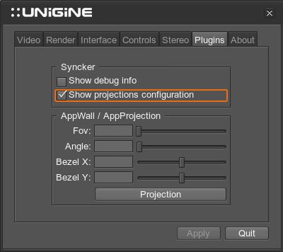
- Go to the Plugins tab and enable the Show projection configuration option in the Syncker group:
The setup mode will become available:
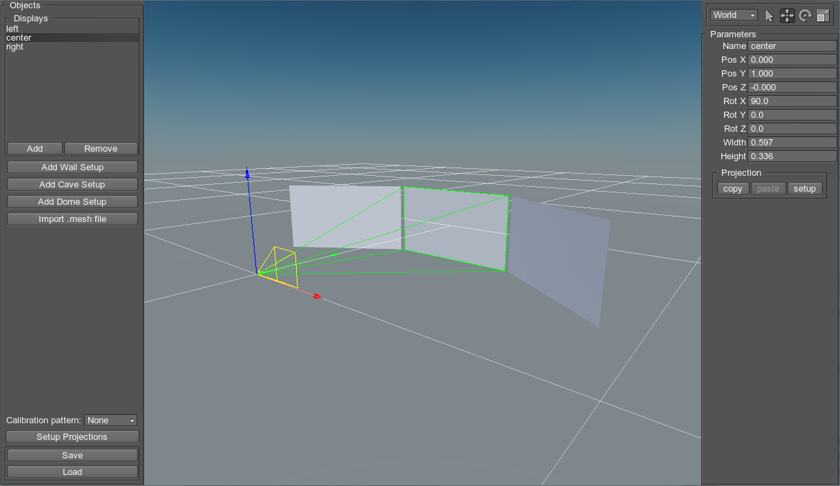
To navigate the scene, use the way like that of the Editor 2 Scene navigation.
If a display is selected, you can focus the camera on it by pressing F key.
The viewer is positioned in the center of the scene and corresponds to the main master camera.
To set up a projection configuration, you should perform the following steps:
- Add the required number of displays.
- Form the projection setup by adjusting the required parameters of the displays.
- Click Setup Projections and adjust the required projections.
Configuration Requirements
Screen/projection configuration for the Syncker should meet the following requirements:
- Each display in the configuration should correspond to one of the monitors/projectors.
- Position and orientation of each display must be relative to the main master camera. The closer the monitor is to the viewer, the higher the FOV value.
Create Displays
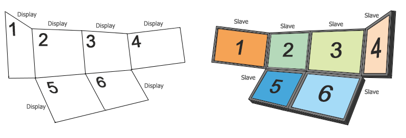
If you are going to use a multi-monitor setup, you will need to add the required number of displays and adjust its transformation and size.
To add a new display, press the Add button on the Objects panel. The default display named display will be added. Each display corresponds to one of the monitors/projectors.
It is also possible to generate automatic virtual environment setups.
Wall Setup
Wall preset is useful to generate a multi-monitor setup of displays formed as an array.
Choose Add Wall Setup to open the Wall Generator window.
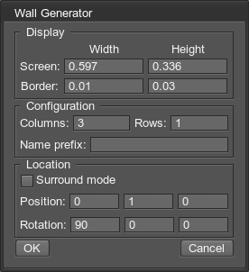
The Wall Generator has the following parameters:
| Screen Width, Screen Height | Size of each display in setup. |
|---|---|
| Border Width, Border Height | Distance between displays along the axis corresponding to displays' width and height. |
| Columns | Number of columns. |
| Rows | Number of rows. |
| Name Prefix | Name prefix for each display in setup. |
| Surround Mode | Defines whether displays are placed on a flat surface or on a sphere while being oriented to the viewer. |
| Position | Position offset for the group of displays. Notice This parameter is available if the Surround Mode is disabled. |
| Radius | Radius of the sphere which the displays should be placed on. Notice This parameter is available if the Surround Mode is enabled. |
| Rotation | Rotation of the group of displays along all axis. |
Click Ok to generate setup.
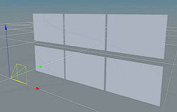
Flat mode
|
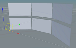
Surround mode
|
CAVE Setup
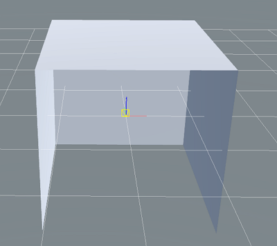
The CAVE (Cave Automatic Virtual Environment) multi-projector setup generation is supported:
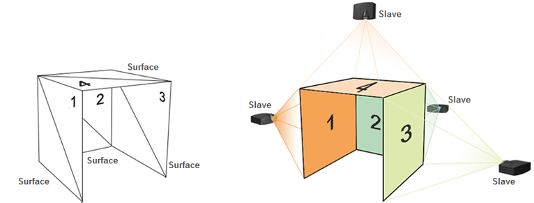
Choose Add Cave Setup to open the Cave Generator window.
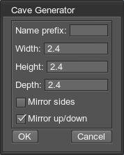
The Cave Generator has the following parameters:
| Name Prefix | Name prefix for each display in setup. |
|---|---|
| Width | Width of the whole setup. |
| Height | Height of the whole setup. |
| Depth | Depth of the whole setup. |
| Mirror Sides | Defines whether side displays should be flipped horizontally. |
| Mirror Up/Down | Defines whether up and down displays should be flipped horizontally. |
Click Ok to generate setup.
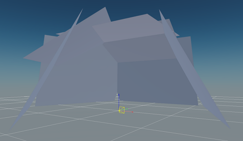
Dome Setup
The Dome multi-projector setup generation is supported:
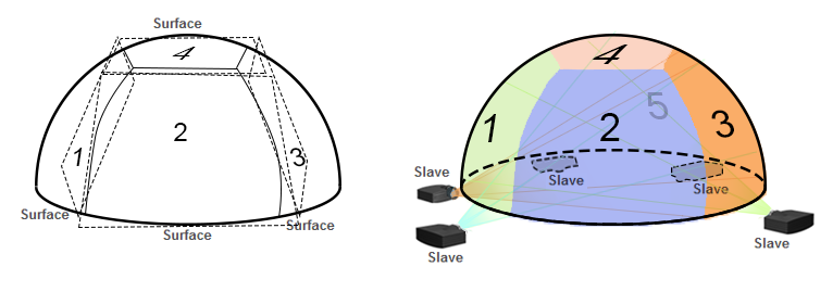
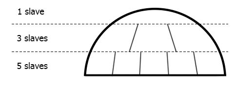
The Dome projection is usually built of several layers of projectors from bottom to top. For example, the 5-3-1 setup describes configuration that has 5 projectors on the lowest layer, 3 on the middle one and 1 projector oriented on the ceiling top.
Choose Add Dome Setup to open the Dome Generator window.
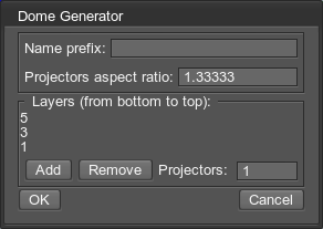
The Dome Generator has the following parameters:
| Name Prefix | Name prefix for each display in setup. |
|---|---|
| Projectors aspect ratio | The proportional relationship between displays width and height. |
| Layers | The list of layers in setup. Use the Add and Remove buttons to manage the list of layers. |
| Projectors | Number of projectors (displays) in the selected layer. |
Click Ok to generate setup.
Import Mesh
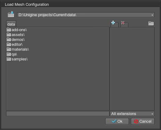
Also, configurations from the previous versions of the Syncker Plugin are supported. To import configuration in the *.mesh format, choose Import Mesh on the Objects panel and then select the desired file in the Load Mesh Configuration dialog.
Configuring Displays
Selecting and Positioning Displays
To select a single display, choose  on the toolbar or by pressing Q on the keyboard and perform left mouse click on the display. You can also select a display by using the Objects panel.
Hold Shift key to add a display to selection, Ctrl - to remove.
Use the transform tools to manually transform a display or several displays the same way as in the Editor 2.

Use the pivot tool to choose between the pivot modes: World or Local, so you can transform displays just the way it is made in the Editor 2.

Display Parameters
To configure the selected display, adjust parameters on the Parameters panel:
To delete a display, press the Remove button or Delete key.
Setting Up Projections
A projection for the display is adjusted via the Projection Configurator window that is opened by pressing the Setup Projections button on the Objects panel:
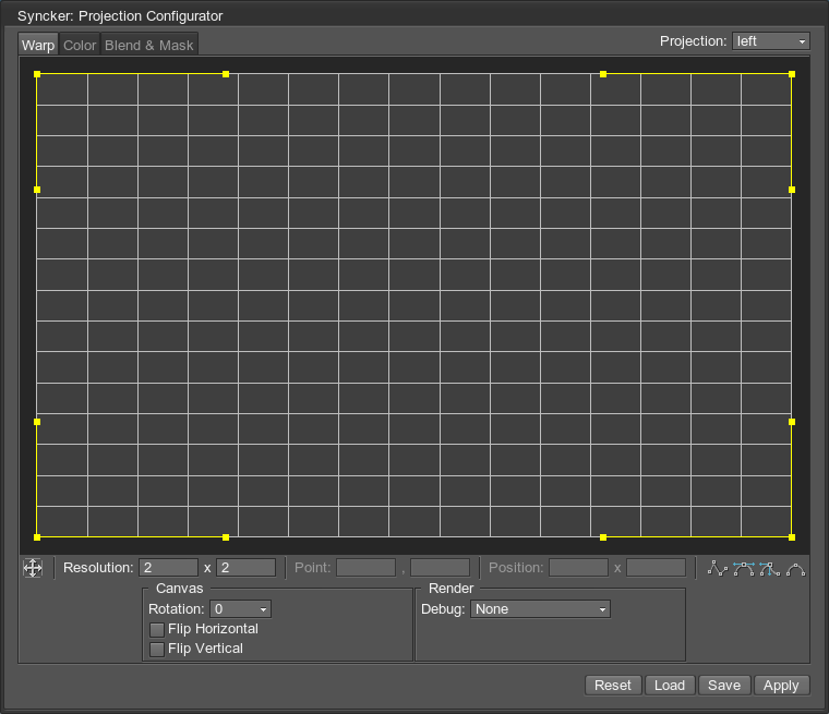
Use the following buttons in the Projection group on the Parameters panel to:
- Copy the projection configuration of the selected display.
- Paste the projection configuration to the selected display(-s).
- Setup the projection configuration of the selected display.

A projection can be saved to the .proj file: each file stores a single projection. All projections used in the configuration are saved to the .sync file.
Calibration
For proper configuration you can enable the Calibration Pattern on the Objects panel. It represents the grid pattern projected on a certain shape which is useful to calibrate displays by avoiding the image distortion. There are the following options:

- None - no pattern applied, the engine viewport is rendered in each display.
-
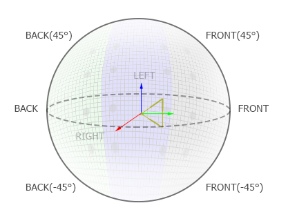
Sphere - the Sphere test pattern is shown by displays.
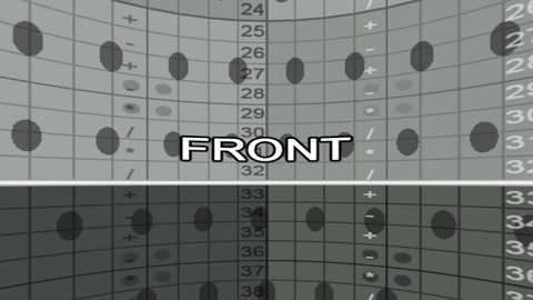
Directions are marked with angles for convenience:
-
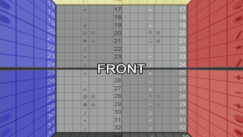
Box - the Box test pattern is shown by displays.
Saving and Loading Configurations
After the screen/projection configuration is set up, it can be saved into a .sync file to be loaded at any time:
- To save the configuration, press the Save button on the Objects panel.
- To load the configuration for editing, press the Load button on the Objects panel.