Создание собственных материалов
As already mentioned, it is the shader code that is the basis of materials, which actually draws them, taking into account the given parameters, states, textures, etc. And for a long time, programming skills were required to create your own materials.Как мы уже говорили, именно шейдерный код является основой материалов, который собственно и рисует их, учитывая заданные параметры, режимы, текстуры и т. д. И долгое время для создания собственных материалов требовались навыки программирования.
UNIGINE has a visual Material Editor — a powerful tool for 3D artists, which not only saves them from the necessity to know how to write code, but also makes working with materials more convenient. And the result is visible immediately when making any changes and saving the graph, which greatly speeds up iterative development. Most operations are performed by simply connecting different nodes into a graph. The graph can be used to quickly prototype and create complex materials, as well as various special effects for surfaces and objects.В UNIGINE есть Визуальный редактор материалов — мощный инструмент для 3D-художников, который не только избавляет их от необходимости уметь писать код, но и делает работу с материалами более удобной. Причем результат виден сразу же при внесении каких-либо изменений и сохранении графа, что значительно ускоряет итеративность разработки. Большинство операций выполняются простым соединением различных функциональных узлов (нод) в граф. С его помощью можно быстро прототипировать и создавать сложные материалы, а также различные спецэффекты для поверхностей и объектов.
Key features:Ключевые особенности:
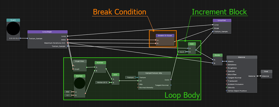
- Loops are a complex but very cool feature that allows repeating arbitrary sequences of actions many times. We have developed our own implementation of loops in graph, which is almost as good as loops written in code, but much easier to use.Циклы – сложная, но очень крутая функция, которая позволяет повторять произвольные последовательности действий множество раз. Мы разработали собственный вариант реализации циклов в графе, который почти так же хорош, как и циклы, написанные в коде, но гораздо проще в использовании.
- Portals help to avoid visual noise in complex graphs by hiding a web created by numerous edges.Порталы позволяют избежать визуального шума в сложных графах, скрывая сложные переплетения ребер.
- Connectors are a special "collapsed" mode of a node, so that it takes up much less space and can be connected to another node in the graph.Коннекторы – специальный “свернутый” режим ноды, благодаря которому она занимает гораздо меньше места и может быть присоединена к другой ноде графа.
- Expressions are used for simple mathematical operations, but much more importantly, they can also be used as swizzles for sampling or changing the number or order of components.Выражения используются для простых математических операций, но гораздо важнее то, что их можно использовать и как свизлы для выборки, изменения числа или порядка компонентов.
- Subgraphs are created by combining graph fragments and can be used in other materials. It is important to note here that any change to a subgraph is automatically propagated to all graphs where it has been used.Подграфы создаются путем объединения фрагментов графов, которые в дальнейшем могут быть использованы в множестве других материалов. Важно отметить, что изменения подграфа автоматически распространяются на все графы, где он был использован.
Working with Material EditorРабота с визуальным редактором материалов#
Let's create a new material graph by right-clicking in the Asset Browser and selecting Create Material → Material Graph in the context menu.Создадим новый граф материала, щелкнув правой кнопкой мыши в Asset Browser и выбрав Create Material → Material Graph.
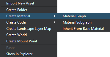
The *.mgraph asset represents both the base material graph (which can be edited using the material editor) and a regular base material — the result of graph compilation — you can assign it to objects in the scene or inherit from it a whole hierarchy of child materials without having to rebuild the graph again. Double-clicking on such an asset will open the Material Editor: Ассет *.mgraph представляет собой как исходный граф материала (редактировать который можно при помощи визуального редактора), так и обычный базовый материал — результат компиляции графа, который можно назначить объектам сцены или отнаследовать от него целую иерархию дочерних материалов не пересобирая граф снова и снова. Двойной щелчок по такому ассету откроет визуальный редактор:
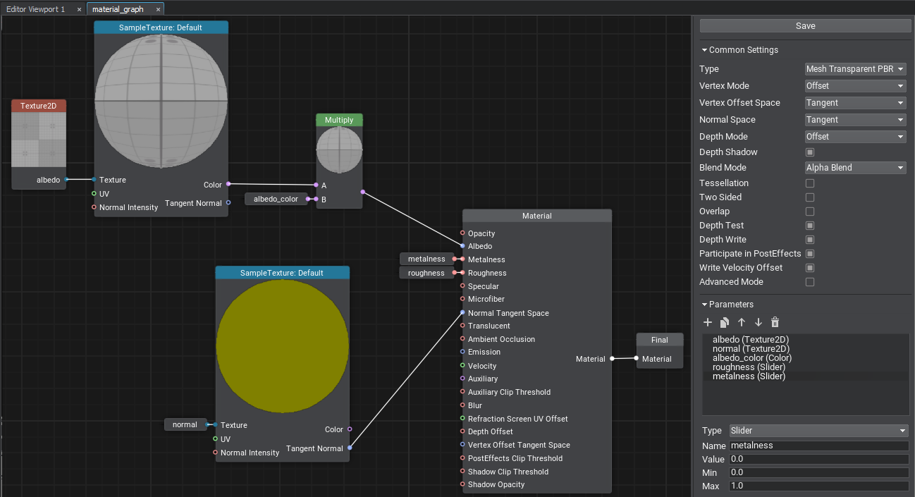
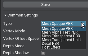
The Material Editor window includes the material graph itself and the Settings panel. The material type determines to what type of node the material can be applied (meshes, decals, or post effects), at what stage of frame rendering the surfaces with this material assigned will be rendered, and the set of supported features and parameters:Окно редактора материалов включает в себя непосредственно граф материала и панель настроек. Тип материала определяет, где может применяться материал (меши, декали или пост-эффекты), на каком этапе рендеринга кадра будут рендериться поверхности с ним, а также набор поддерживаемых функций и параметров:
Other settings allow selecting the basis space to be used, activating various features such as emission, tessellation, and controlling the shader compilation settings. Остальные настройки позволяют выбрать используемые базисные пространства, активировать различные функции, такие как эмиссия, тесселяция, и управлять настройками компиляции шейдеров.
Nodes and PortsНоды и порты#
A material graph consists of nodes — functional blocks responsible for processing input data and connected to each other using edges. By assembling the graph and applying different math, we define the appearance of the material. The Save button saves the graph and compiles it into a material.Граф материала состоит из нод — функциональных блоков, отвечающих за обработку входных данных и соединяемых между собой при помощи ребер. Собирая граф и применяя различную математику, мы определяем внешний вид материала. Кнопка Save сохранит граф и скомпилирует его в материал.
The Material node is the main node of your material. It provides a set of input graph data and generates a material of a certain type depending on the current settings.Нода Material является главной нодой вашего материала. Она предоставляет набор входных графических данных и генерирует материал определенного типа в зависимости от текущих настроек.
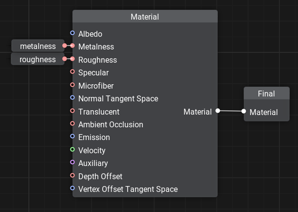
For example, for PBR materials we can control Albedo, Metalness, Roughness, Specular, Microfiber, and Normal values that define the surface properties.К примеру, для PBR-материалов мы можем контролировать Albedo, Metalness, Roughness, Specular, Microfiber и Normal значения которые определяют свойства поверхности.
The Material node output is connected with the Final node, which is the main node of the output material.Выход ноды Material соединяется с Final-нодой — основной нодой выходного материала.
Nodes have ports to connect to each other and transfer data, they define the input (left side) or output (right side). Connecting edges to the ports ensures that data is transferred through the material graph node network and processed.Для соединения между собой и передачи данных у нод есть порты, они определяют вход (слева) или выход (справа). Подключение ребер к портам обеспечивает передачу данных по сети нод графа материалов и их обработку.
Each port has a data type that defines the edges that can be connected to it (float, float4, matrix, texture, etc.). There is an automatic type conversion for convenience.Каждый порт имеет тип данных, определяющий ребра, которые могут быть к нему подключены (float, float4, matrix, texture и т.д.). Для удобства имеется автоматическое преобразование типов.
A quick chart on data types and their indications:Небольшая шпаргалка по типам данных и их индикациям:
 float
float |
 float2
 |
 float3
 |
 float4
 |
 int
int |
 int2
int2 |
 int3
int3 |
 int4
int4 |
 matrix — a matrix of float values: float2×2, float3×3, float4×4.
 matrix — матрица float значений: float2×2, float3×3, float4×4.
 |
|||
 texture — any type of a texture: Texture 2D, Texture 3D, Texture 2D Array, Texture 2D Int and Texture Cube.
 texture — любой тип текстуры: Texture 2D, Texture 3D, Texture 2D Array, Texture 2D Int and Texture Cube.
 |
|||
 bool — a boolean value used in logical nodes and loops.
 bool — логическое значение, используемое в логических нодах и циклах (loops).
 |
|||
 any — arbitrary data type meaning the port supports several data types.
 any — произвольный тип данных означает, что порт поддерживает несколько типов данных.
 |
|||
 error — indicates an error (e.g., no required input provided or type conversion has failed).
 error — указывает на ошибку (например, не предоставлен требуемый ввод или не удалось преобразовать тип).
 |
|||
Only one edge can be connected to any input port, but you can connect multiple edges to an output port.К любому входному порту можно подключить только одно ребро, но к выходному порту можно подключить несколько ребер.
Ports have adapters that allow you to select data components in any order, combine, and reorder them, providing easy access to elements and more flexibility, thus minimizing unnecessary graph complexity.У портов есть адаптеры, которые позволяют выбирать компоненты данных в произвольном порядке, комбинировать и переупорядочивать их, обеспечивая удобный доступ к элементам и большую гибкость, за счет чего минимизируется излишнее усложнение графа.

Example: we can choose which 3 components of albedo_color (float4) will be used as float3.Пример: мы можем выбрать, какие 3 компонента albedo_color (float4) мы хотим использовать в качестве float3.
Adding New NodesДобавление новых нод#
To add a new node, right-click on the background or press the Space button and select the node type from the palette, or type its name in the search field.Чтобы добавить новую ноду, щелкните правой кнопкой мыши по фону или нажмите «Пробел» и выберите тип ноды из палитры, либо введите его имя в поле поиска.
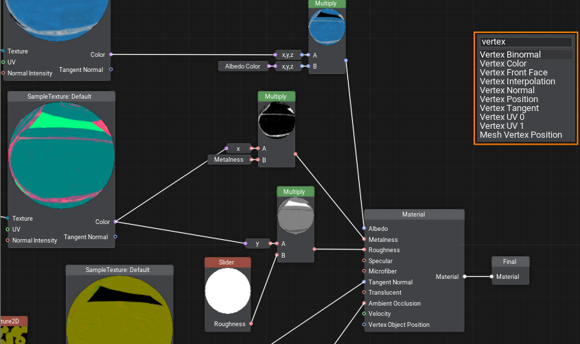
Dragging an edge from an input port opens a node creation palette with a pre-set filter to the required data type for the corresponding port.Вытягивание ребра из входного порта открывает палитру создания ноды с предустановленным для этого порта фильтром требуемого типа данных.
Note: using Ctrl+C and Ctrl+V you can not only copy entire graphs within one material or from other materials, but also share them with other developers, because graphs are copied in text format. It is enough to copy the resulting text and paste it into the Material Editor window to get a ready graph.Заметьте: при помощи Ctrl+C и Ctrl+V можно не только копировать целые графы в пределах одного материала или между несколькими, но и делиться с другими разработчиками, ведь копирование графов производится в текстовом формате. Достаточно скопировать полученный текст и вставить в окно редактора материалов Material Editor, чтобы получить готовый граф.
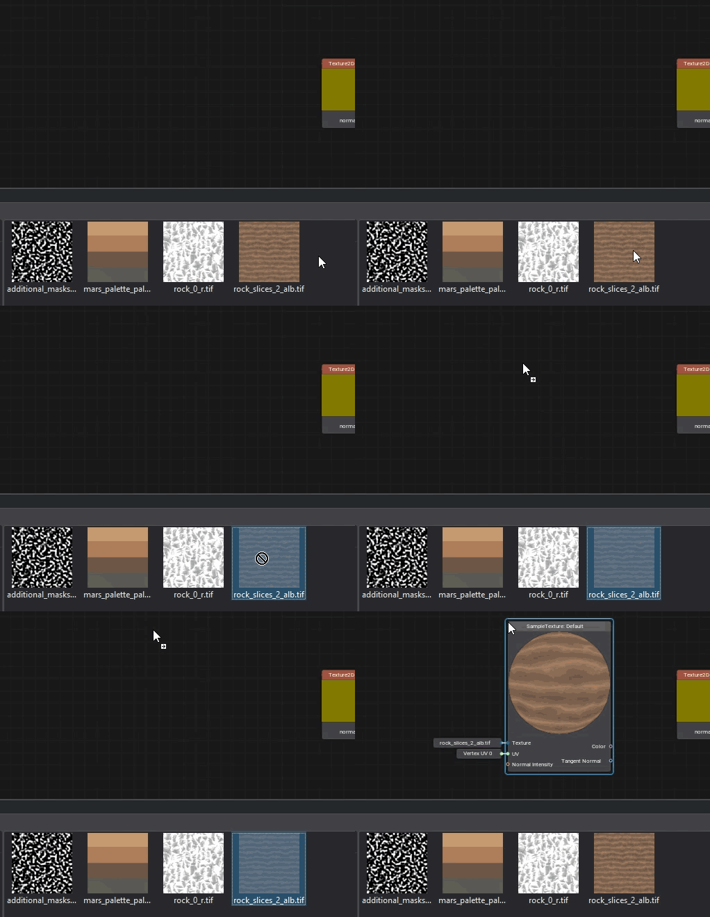
Textures can be dragged directly from the Asset Browser. In this case, a Sample Texture node with corresponding settings will be added automatically.Текстуры можно перетаскивать прямо из Asset Browser. В этом случае автоматически добавится нода Sample Texture с соответствующими настройками.
ParametersПараметры#

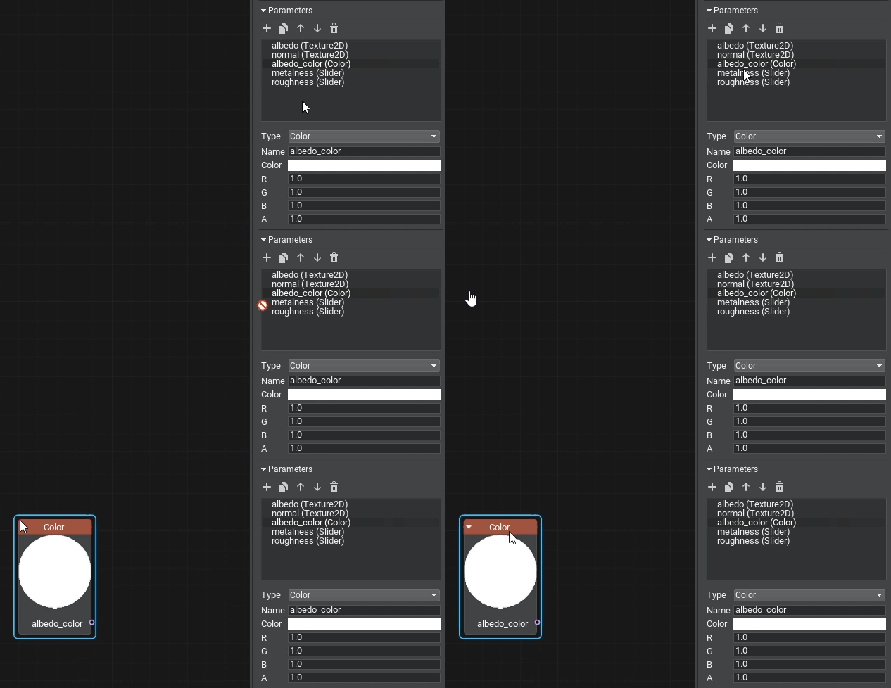
To make values available for further editing, you should explicitly define material parameters by specifying their type, default value, and other options. They can be grouped for convenience.Чтобы сделать значения доступными для дальнейшего редактирования, надо явно определить параметры материала, указав их тип, значение по умолчанию и другие опции. Для удобства их можно группировать.
It is enough to drag a parameter into a graph to use it as a node.Параметр достаточно перетащить в граф, чтобы использовать как ноду.
Errors and WarningsОшибки и предупреждения#
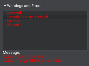
If the built graph has any issues, you will see the Warnings and Errors block in the Settings panel: select an element in the list to learn the details and find the node in the graph that causes an issue, then try to fix it.Если в собранном графе есть какие-то проблемы, то в панели настроек Settings вы увидите блок Warnings and Errors – выберите элемент в списке, чтобы узнать детали и найти проблемную ноду в графе и попытаться ее исправить.
Organizing GraphsУпорядочивание графов#
Sometimes, especially in graphs of complex materials, too many intersecting edges make the workspace look like a web and the data flow is incomprehensible. Therefore, it is very important to learn how to organize graphs to improve the perception and simplify the work with them.Иногда, особенно в графах сложных материалов, слишком много пересекающихся ребер делают рабочее пространство похожим на паутину, а поток данных очень трудно понять. Поэтому очень важно научиться упорядочивать графы для улучшения восприятия и облегчения работы с ними.
UNIGINE 2 has several tools in Material Editor for this purpose: loops, portals, and subgraphs. Let's review each of them in detail.Для этого в визуальном редакторе материалов UNIGINE 2 существует несколько инструментов: циклы, порталы и подграфы. Далее расскажем про каждый инструмент подробнее.
LoopsЦиклы (Loops)#
When you need to perform a certain action several times, cloning the corresponding group of nodes will quickly make your graph overcomplicated, even if only 10 iterations are required. In UNIGINE, you can create loops for this purpose, just like in programming.Когда нужно выполнить определенные действия несколько раз, клонирование соответствующих групп нод очень быстро сделает ваш граф слишком сложным, даже если требуется всего 10 итераций. В UNIGINE для этого можно создавать циклы, как и в программировании.
To create a loop, simply add the Loop Begin and Loop End nodes and connect their Loop ports.Чтобы создать цикл, нужно просто добавить ноды Loop Begin и Loop End и соединить их порты Loop.
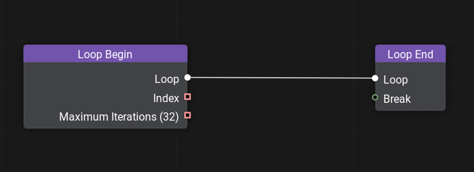
Double-click on the Loop Begin node to open the loop constructor window and set the variables that change with each iteration of the loop and the total number of iterations. See the documentation for details on creating loops.Двойным кликом на ноде Loop Begin можно открыть окно конструктора цикла и задать в нем переменные, меняющиеся с каждой итерацией цикла, и общее число итераций. Подробности создания циклов смотрите в документации.
PortalsПорталы#
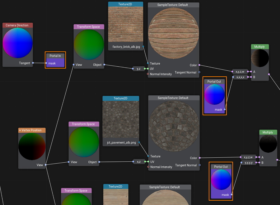
A portal is a set of special nodes that has one input (Portal In) and one or more outputs (Portal Out) all having the same name. Portals serve to reduce the number of intersecting edges and make the graph more 'readable'.Портал — это набор специальных нод, включающий один вход (Portal In) и один или несколько выходов (Portal Out), связанных с входом по имени. Порталы служат для уменьшения количества пересекающихся ребер и делают граф более «читабельным».
SubgraphsПодграфы#
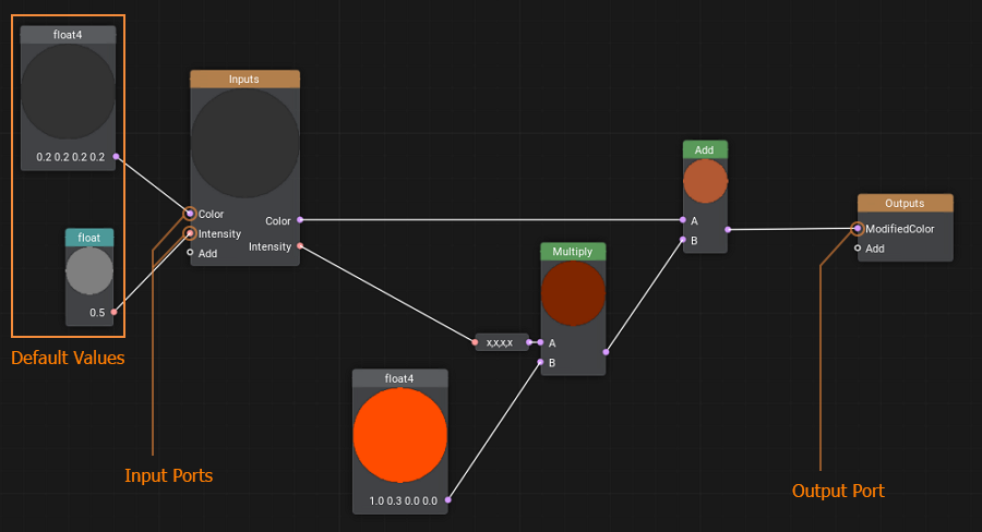
A subgraph is a special type of material graph that can be referenced from inside other material graphs. This can be very useful when the same operation is to be performed multiple times in a single graph or across multiple graphs.Подграф — это особый тип графа материалов, на который можно ссылаться внутри других графов материалов. Это может быть очень полезно для переиспользования логики, когда одни и те же операции должны выполняться несколько раз в одном или нескольких графах.
You simply pack these operations into a box with a set of inputs and outputs and then use this box anywhere you need.Просто упаковываем эти операции в коробку с набором входов и выходов и затем используем эту коробку везде, где нужно.
Custom CodeПользовательский код#
No matter how advanced the material system is, sometimes it can be faster to write a few lines of code for math operations than to create a bunch of nodes and connect them. There is an easy solution — create a Function node and wrap any shader function in it. The input and output ports for the node will be generated automatically according to the function signature.Независимо от того, насколько продвинута система материалов, иногда может быть быстрее написать несколько строк кода для математических операций, чем создавать кучу нод и соединять их. Решение простое — создать ноду Function и обернуть в нее любую шейдерную функцию. Входные и выходные порты для ноды будут генерироваться автоматически в соответствии с сигнатурой функции.
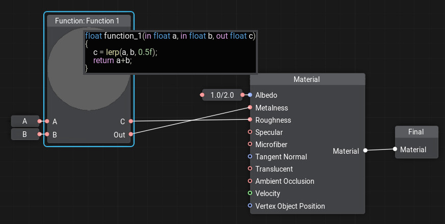
To add or edit code in the node, double-click the node and the code editor window will open. You can write as many functions as you need, the last function in the code will be considered the main function.Чтобы добавить или отредактировать код в ноде, нужно дважды щелкнуть ноду и откроется окно редактора кода. Можно написать столько функций, сколько нужно, последняя функция в коде будет считаться главной.
Creating a Material in Material EditorСоздаем свой материал в визуальном редакторе#
Let's create a wall material with the ability to blend two albedo textures by mask. This material can be used to simulate a multi-layered material where some layers show through others, such as an old or stylized plastered wall with brickwork visible in areas where plaster has fallen off. Our new material will have two albedo textures, we will blend them using Custom Surface Texture as a single channel mask, which will determine how clearly the second texture shows up on the first (in areas where the mask has black color the albedo1 texture will be painted, and albedo2 in white areas).Давайте создадим материал для стен и добавим возможность смешивания двух текстур альбедо по маске. С помощью него можно смоделировать многослойный материал, в котором одни слои проступают под другими, например, старую или стилизованную оштукатуренную стену с видимой в областях разрушения слоя штукатурки кирпичной кладкой. Наш новый материал будет иметь 2 текстуры альбедо, их мы будем смешивать используя текстуру Custom Surface Texture как одноканальную маску, которая будет определять насколько отчетливо вторая текстура проступает на первой (в областях, где маска имеет черный цвет будет рисоваться текстура albedo1, а в белых областях – albedo2).
-
Let's create a new material graph by right-clicking in the Asset Browser and selecting Create Material → Material Graph:Создадим новый граф материала, щелкнув правой кнопкой мыши в Asset Browser и выбрав Create Material → Material Graph:

and name it albedo_mixer.и назовем его albedo_mixer.
- Open the Material Editor by double-clicking on the created *.mgraph asset.Откроем визуальный редактор двойным щелчком по созданному ассету *.mgraph.
- In the list of parameters, find the albedo texture and rename it to albedo1.В списке параметров найдем текстуру albedo и переименуем ее в albedo1.
-
Add the second albedo texture to parameters, so that either of them could be assigned. To do this, click + in the Parameters section, then in the dialog box for Type choose Texture2D, in Name enter the name of the new texture – albedo2, and click Ok.Добавим в параметры вторую текстуру альбедо, чтобы можно было назначить любую. Для этого щелкнем + в блоке Parameters, затем в диалоговом окне для Type выберем Texture2D а в Name введем имя новой текстуры – albedo2, и нажмем Ok.
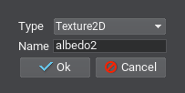
- To use the new parameter in the graph as a node just drag it to the working space.Чтобы использовать новый параметр в графе в виде ноды просто перетащим его.
- Drag the Texture2D node output, type Sample Texture in the constructor panel and press Enter.Теперь, потянем выход ноды Texture2D, наберем в появившемся меню добавления ноды Sample Texture и нажмем Enter.
- Drag the UV input of the Sample Texture node, type in Vertex UV0 and select the corresponding node from the list.У ноды Sample Texture потянем за вход UV, введем Vertex UV0 и выберем в списке соответствующую ноду.
- Add the Lerp node that will perform linear interpolation between the colors of the albedo1 and albedo2 textures with a coefficient from the mask. Connect the Color output of the Sample Texture node taking the value from albedo1 to input A, and the Color output from the Sample Texture node connected to albedo2 — to input B.Далее добавим ноду Lerp, которая будет осуществлять линейную интерполяцию между цветами текстур albedo1 и albedo2 с коэффициентом из маски. Соответственно ко входу A подключим выход Color от ноды Sample Texture, берущей значения из albedo1, а ко входу B подключим выход Color от ноды Sample Texture, подключенной к albedo2.
-
And the last item to be added is the interporation coefficient. Create the Surface Custom Texture node and add the Sample Texture node for it (as we already did by connecting Vertex UV0 to the UV input). Drag the Color output from this node to the Coefficient input of the Lerp node and select the X,X,X,X adapter because we need only the first channel.Осталось добавить коэффициент интерполяции. Создадим ноду Surface Custom Texture и для нее добавим ноду Sample Texture (как мы уже делали, подав Vertex UV0 на вход UV). Выход Color от этой ноды потянем ко входу Coefficient ноды Lerp и, поскольку нам нужен только первый канал, выберем адаптер X,X,X,X.
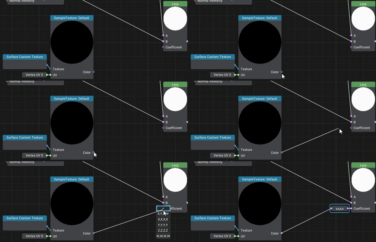
-
The resulting graph should look as follows.В итоге у нас должен получиться такой граф.
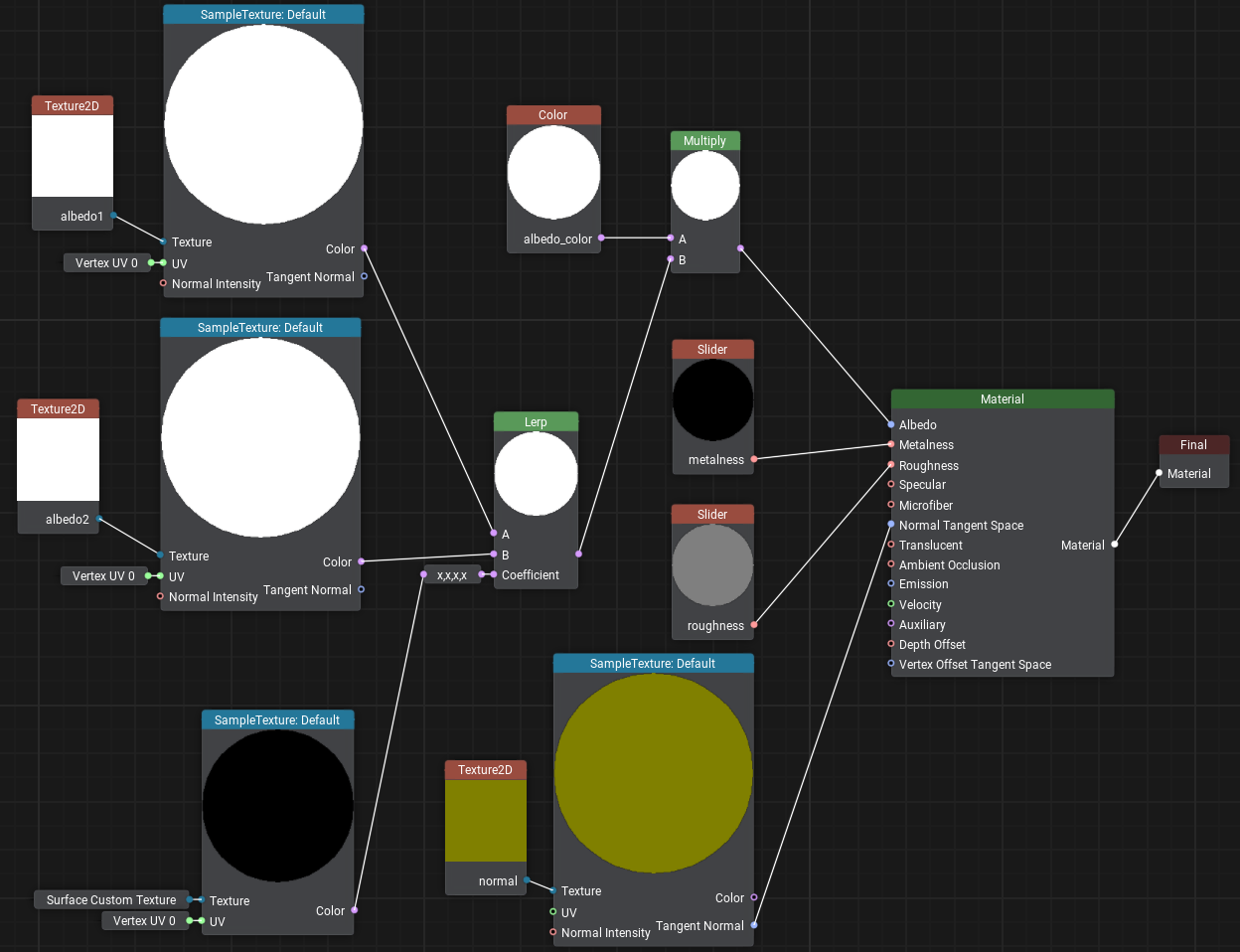
- Save it by clicking the Save button and close the Material Editor.Сохраним его, нажав Save, и закроем Редактор материала.
- Now let's assign this material to the wall by dragging it directly from the Asset Browser and inherit a user material from it by clicking Create a child material in order to assign your own textures.Теперь назначим этот материал на стену перетащив его прямо из Asset Browser. И отнаследуем от него пользовательский материал, чтобы назначить свои собственные текстуры – для этого щелкнем Create a child material.
-
Download and drag the following images to the Asset Browser, after importing drag wall_brick.jpg and wall_plaster.jpg to the Albedo1 and Albedo2 fields accordingly.Скачайте следующие изображения wall_brick.jpg и wall_plaster.jpg в Asset Browser и после успешного импорта перетащите их в поля Albedo1 и Albedo2 соответственно.
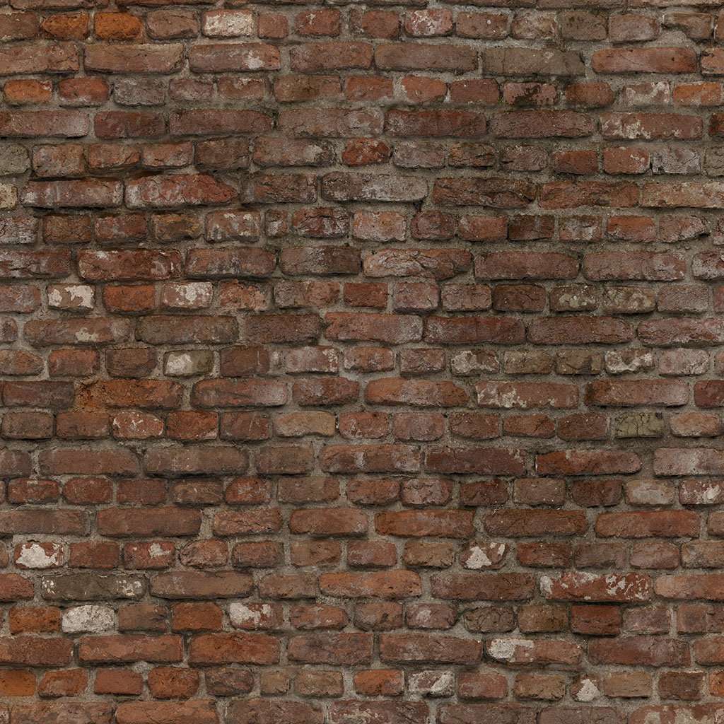
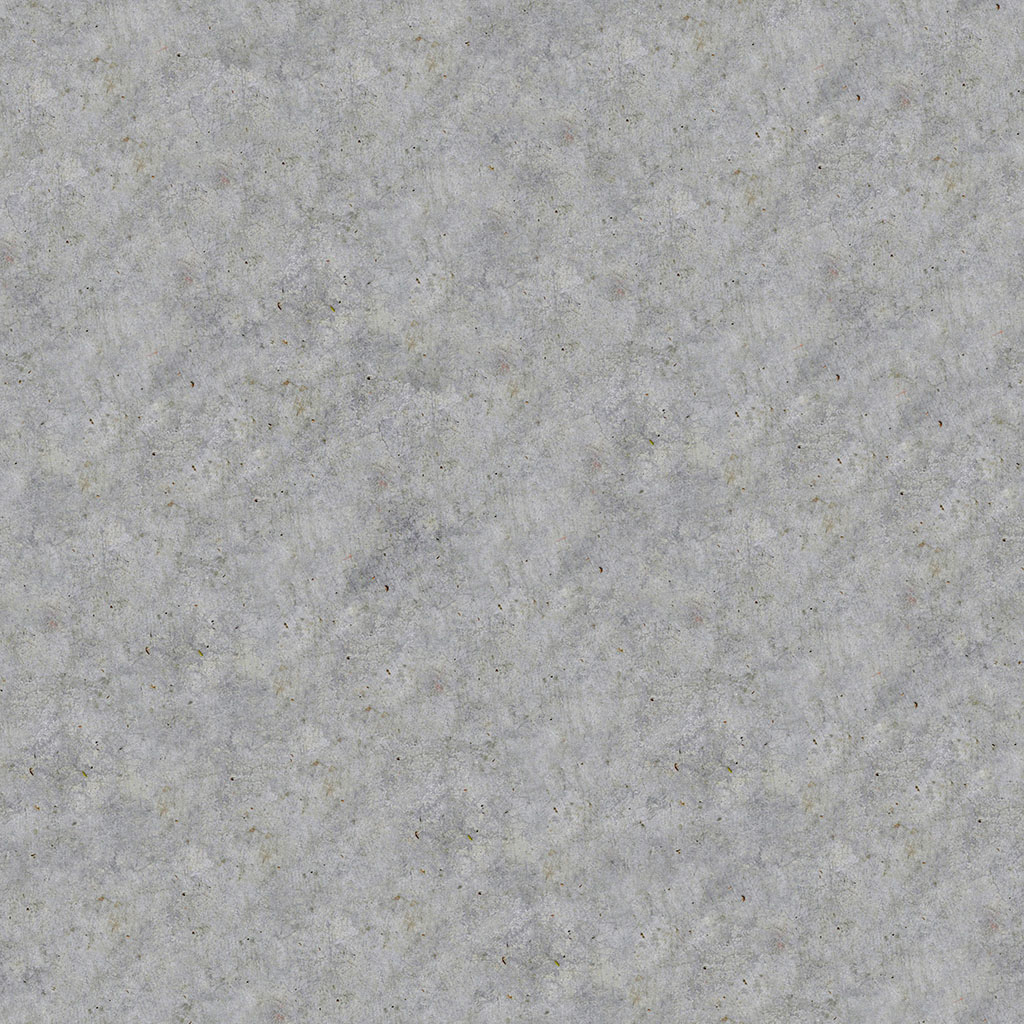
Now we need to determine areas where the brick will show through under the plaster. To do this, select the wall and turn on Surface Custom Texture in the Surfaces section of the Parameters window. In the Texture field, first try to assign the standard textures: white.texture and black.texture. You will notice that in one case the wall is completely plastered, and in the second case it a solid brick wall. Now let's create our own mask for this surface — click + to add a new texture.Теперь осталось определить, где из-под штукатурки будет проступать кирпич. Для этого выделим стену и в блоке Surfaces окна Parameters включим Surface Custom Texture. В поле Texture попробуйте сначала назначить стандартные текстуры white.texture, а затем black.texture. Вы увидите, что в одном случае стена полностью заштукатурена, а во втором везде видна кирпичная кладка. Теперь создадим собственную маску для этой поверхности, для этого добавим новую текстуру, щелкнув +.

Set the required size, select R (single-channel mask) in Channels, click OK, and write wall_mask as the new texture name.Задайте желаемый размер, в Channels выберите R (одноканальная маска), нажмите OK и укажите имя новой текстуры wall_mask.
In the next section, we'll learn how to draw the mask directly on the object using the brush to mark the areas where we want to see brickwork. To do this, UNIGINE we'll use the Texture Editor tool.В следующем разделе разберемся с тем, как нарисовать маску прямо на объекте, при помощи кисти отмечая области, где мы хотим видеть кирпичную кладку. Для этого в UNIGINE есть редактор текстур (Texture Editor).
Информация, представленная на данной странице, актуальна для версии UNIGINE 2.19.1 SDK.

