Creating Your Own Materials
As already mentioned, it is the shader code that is the basis of materials, which actually draws them, taking into account the given parameters, states, textures, etc. And for a long time, programming skills were required to create your own materials.
UNIGINE has a visual Material Editor — a powerful tool for 3D artists, which not only saves them from the necessity to know how to write code, but also makes working with materials more convenient. And the result is visible immediately when making any changes and saving the graph, which greatly speeds up iterative development. Most operations are performed by simply connecting different nodes into a graph. The graph can be used to quickly prototype and create complex materials, as well as various special effects for surfaces and objects.
Key features:
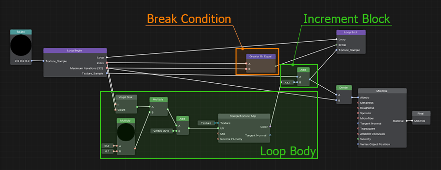
- Loops are a complex but very cool feature that allows repeating arbitrary sequences of actions many times. We have developed our own implementation of loops in graph, which is almost as good as loops written in code, but much easier to use.
- Portals help to avoid visual noise in complex graphs by hiding a web created by numerous edges.
- Connectors are a special "collapsed" mode of a node, so that it takes up much less space and can be connected to another node in the graph.
- Expressions are used for simple mathematical operations, but much more importantly, they can also be used as swizzles for sampling or changing the number or order of components.
- Subgraphs are created by combining graph fragments and can be used in other materials. It is important to note here that any change to a subgraph is automatically propagated to all graphs where it has been used.
Working with Material Editor#
Let's create a new material graph by right-clicking in the Asset Browser and selecting Create Material → Material Graph in the context menu.
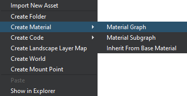
The *.mgraph asset represents both the base material graph (which can be edited using the material editor) and a regular base material — the result of graph compilation — you can assign it to objects in the scene or inherit from it a whole hierarchy of child materials without having to rebuild the graph again. Double-clicking on such an asset will open the Material Editor:
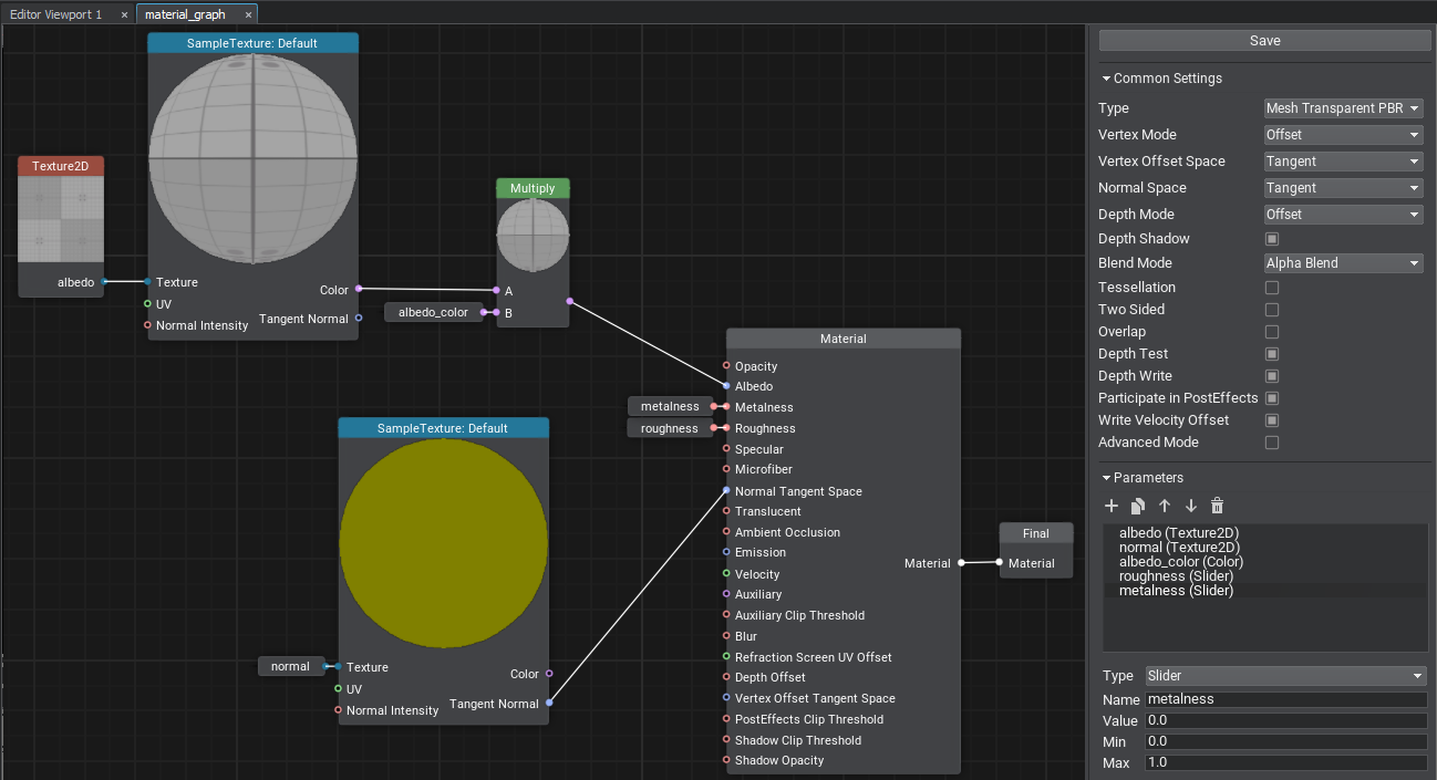
The Material Editor window includes the material graph itself and the Settings panel. The material type determines to what type of node the material can be applied (meshes, decals, or post effects), at what stage of frame rendering the surfaces with this material assigned will be rendered, and the set of supported features and parameters:
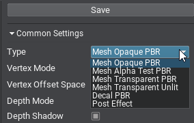
Other settings allow selecting the basis space to be used, activating various features such as emission, tessellation, and controlling the shader compilation settings.
Nodes and Ports#
A material graph consists of nodes — functional blocks responsible for processing input data and connected to each other using edges. By assembling the graph and applying different math, we define the appearance of the material. The Save button saves the graph and compiles it into a material.
The Material node is the main node of your material. It provides a set of input graph data and generates a material of a certain type depending on the current settings.
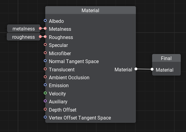
For example, for PBR materials we can control Albedo, Metalness, Roughness, Specular, Microfiber, and Normal values that define the surface properties.
The Material node output is connected with the Final node, which is the main node of the output material.
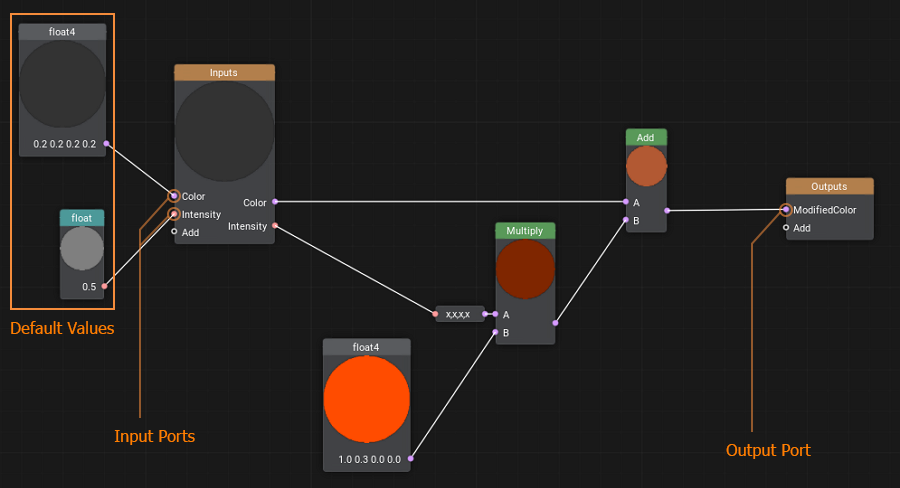
Nodes have ports to connect to each other and transfer data, they define the input (left side) or output (right side). Connecting edges to the ports ensures that data is transferred through the material graph node network and processed.
Each port has a data type that defines the edges that can be connected to it (float, float4, matrix, texture, etc.). There is an automatic type conversion for convenience.
A quick chart on data types and their indications:
 float
float |
 float2
 |
 float3
 |
 float4
 |
 int
int |
 int2
int2 |
 int3
int3 |
 int4
int4 |
 matrix — a matrix of float values: float2×2, float3×3, float4×4.
 |
|||
 texture — any type of a texture: Texture 2D, Texture 3D, Texture 2D Array, Texture 2D Int and Texture Cube.
 |
|||
 bool — a boolean value used in logical nodes and loops.
 |
|||
 any — arbitrary data type meaning the port supports several data types.
 |
|||
 error — indicates an error (e.g., no required input provided or type conversion has failed).
 |
|||
Only one edge can be connected to any input port, but you can connect multiple edges to an output port.
Ports have adapters that allow you to select data components in any order, combine, and reorder them, providing easy access to elements and more flexibility, thus minimizing unnecessary graph complexity.
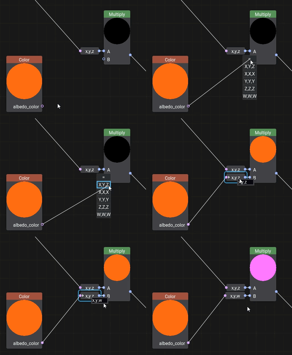
Example: we can choose which 3 components of albedo_color (float4) will be used as float3.
Adding New Nodes#
To add a new node, right-click on the background or press the Space button and select the node type from the palette, or type its name in the search field.
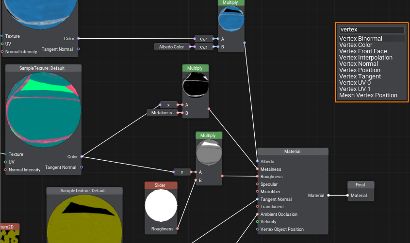
Dragging an edge from an input port opens a node creation palette with a pre-set filter to the required data type for the corresponding port.
Note: using Ctrl+C and Ctrl+V you can not only copy entire graphs within one material or from other materials, but also share them with other developers, because graphs are copied in text format. It is enough to copy the resulting text and paste it into the Material Editor window to get a ready graph.
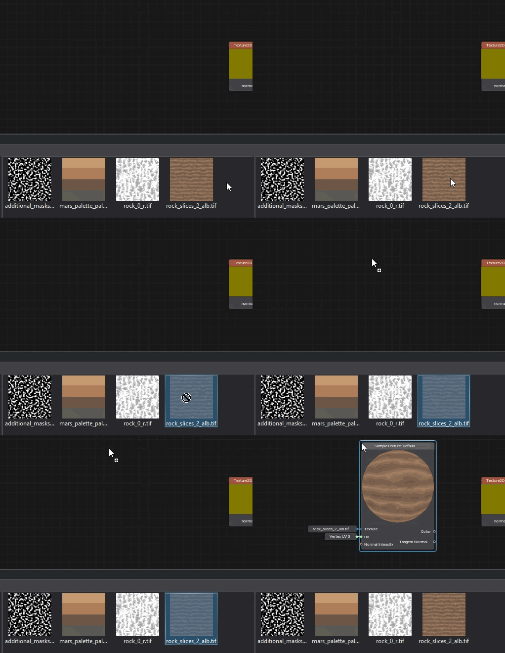
Textures can be dragged directly from the Asset Browser. In this case, a Sample Texture node with corresponding settings will be added automatically.
Parameters#

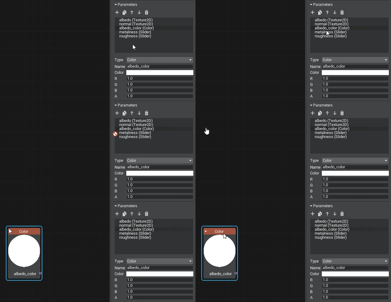
To make values available for further editing, you should explicitly define material parameters by specifying their type, default value, and other options. They can be grouped for convenience.
It is enough to drag a parameter into a graph to use it as a node.
Errors and Warnings#
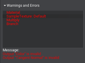
If the built graph has any issues, you will see the Warnings and Errors block in the Settings panel: select an element in the list to learn the details and find the node in the graph that causes an issue, then try to fix it.
Organizing Graphs#
Sometimes, especially in graphs of complex materials, too many intersecting edges make the workspace look like a web and the data flow is incomprehensible. Therefore, it is very important to learn how to organize graphs to improve the perception and simplify the work with them.
UNIGINE 2 has several tools in Material Editor for this purpose: loops, portals, and subgraphs. Let's review each of them in detail.
Loops#
When you need to perform a certain action several times, cloning the corresponding group of nodes will quickly make your graph overcomplicated, even if only 10 iterations are required. In UNIGINE, you can create loops for this purpose, just like in programming.
To create a loop, simply add the Loop Begin and Loop End nodes and connect their Loop ports.
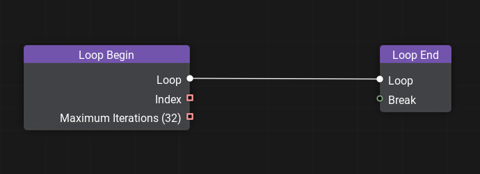
Double-click on the Loop Begin node to open the loop constructor window and set the variables that change with each iteration of the loop and the total number of iterations. See the documentation for details on creating loops.
Portals#
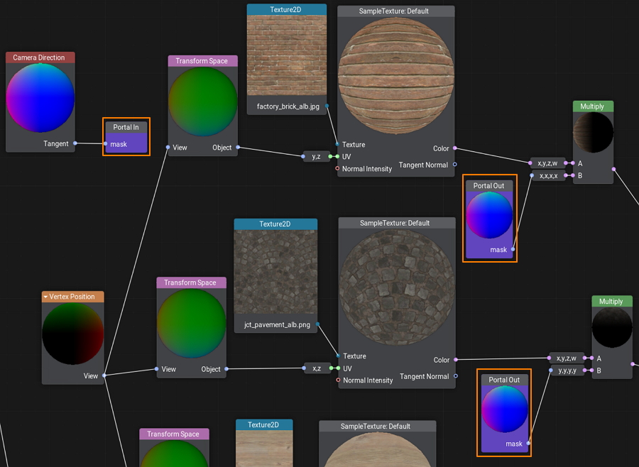
A portal is a set of special nodes that has one input (Portal In) and one or more outputs (Portal Out) all having the same name. Portals serve to reduce the number of intersecting edges and make the graph more 'readable'.
Subgraphs#
A subgraph is a special type of material graph that can be referenced from inside other material graphs. This can be very useful when the same operation is to be performed multiple times in a single graph or across multiple graphs.
You simply pack these operations into a box with a set of inputs and outputs and then use this box anywhere you need.
Custom Code#
No matter how advanced the material system is, sometimes it can be faster to write a few lines of code for math operations than to create a bunch of nodes and connect them. There is an easy solution — create a Function node and wrap any shader function in it. The input and output ports for the node will be generated automatically according to the function signature.
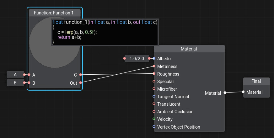
To add or edit code in the node, double-click the node and the code editor window will open. You can write as many functions as you need, the last function in the code will be considered the main function.
Creating a Material in Material Editor#
Let's create a wall material with the ability to blend two albedo textures by mask. This material can be used to simulate a multi-layered material where some layers show through others, such as an old or stylized plastered wall with brickwork visible in areas where plaster has fallen off. Our new material will have two albedo textures, we will blend them using Custom Surface Texture as a single channel mask, which will determine how clearly the second texture shows up on the first (in areas where the mask has black color the albedo1 texture will be painted, and albedo2 in white areas).
-
Let's create a new material graph by right-clicking in the Asset Browser and selecting Create Material → Material Graph:

and name it albedo_mixer.
- Open the Material Editor by double-clicking on the created *.mgraph asset.
- In the list of parameters, find the albedo texture and rename it to albedo1.
-
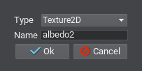
Add the second albedo texture to parameters, so that either of them could be assigned. To do this, click + in the Parameters section, then in the dialog box for Type choose Texture2D, in Name enter the name of the new texture – albedo2, and click Ok.
- To use the new parameter in the graph as a node just drag it to the working space.
- Drag the Texture2D node output, type Sample Texture in the constructor panel and press Enter.
- Drag the UV input of the Sample Texture node, type in Vertex UV0 and select the corresponding node from the list.
- Add the Lerp node that will perform linear interpolation between the colors of the albedo1 and albedo2 textures with a coefficient from the mask. Connect the Color output of the Sample Texture node taking the value from albedo1 to input A, and the Color output from the Sample Texture node connected to albedo2 — to input B.
-
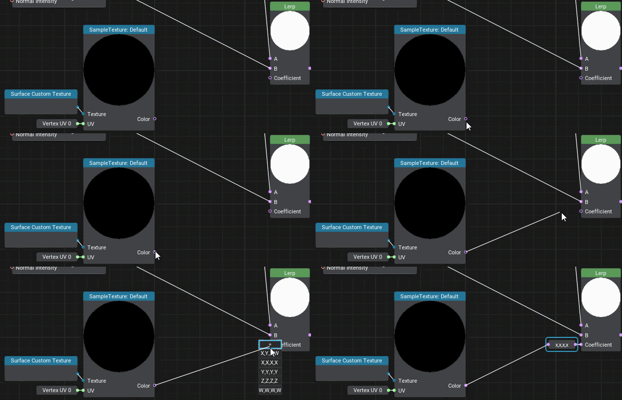
And the last item to be added is the interporation coefficient. Create the Surface Custom Texture node and add the Sample Texture node for it (as we already did by connecting Vertex UV0 to the UV input). Drag the Color output from this node to the Coefficient input of the Lerp node and select the X,X,X,X adapter because we need only the first channel.
-
The resulting graph should look as follows.
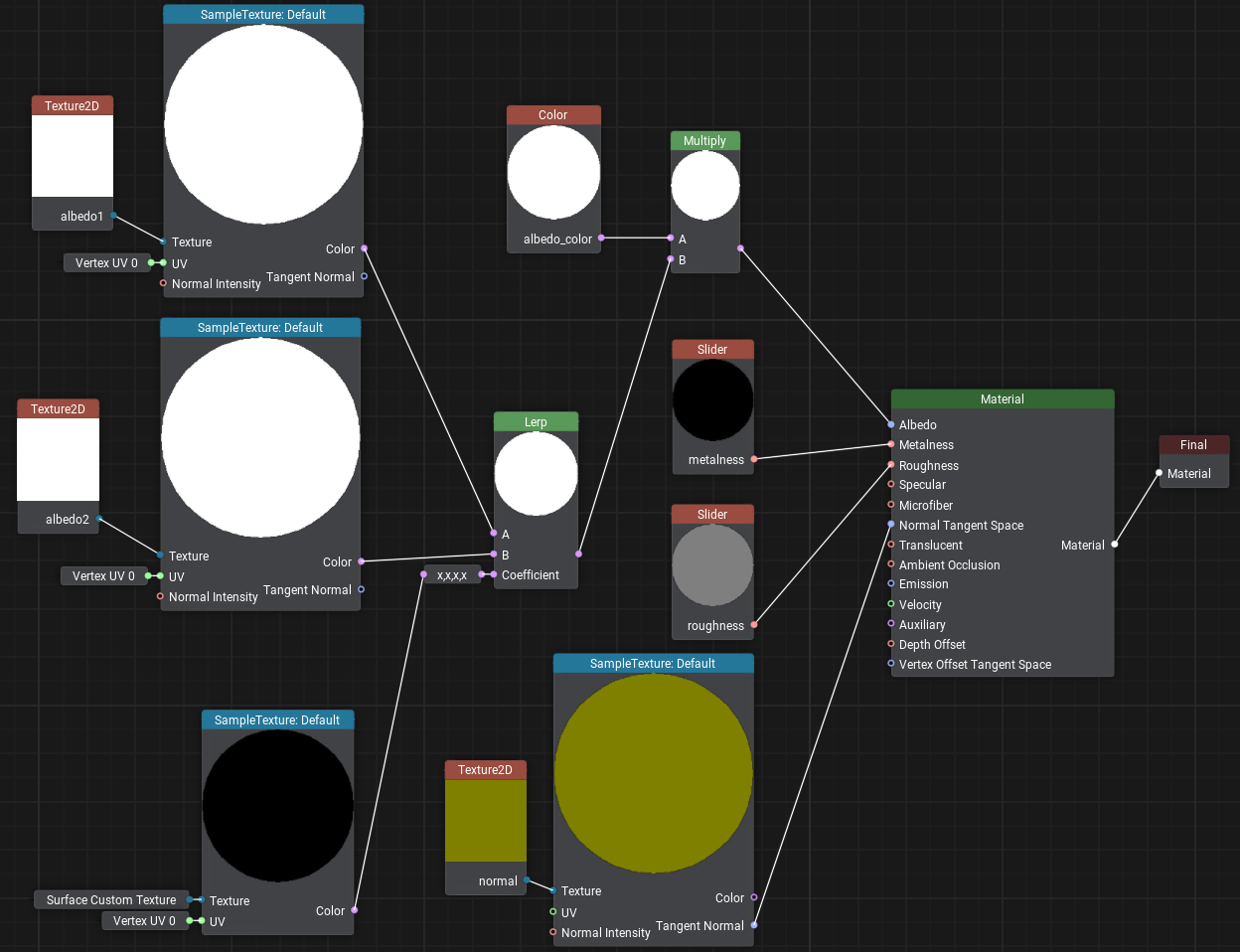
- Save it by clicking the Save button and close the Material Editor.
- Now let's assign this material to the wall by dragging it directly from the Asset Browser and inherit a user material from it by clicking Create a child material in order to assign your own textures.
-
Download and drag the following images to the Asset Browser, after importing drag wall_brick.jpg and wall_plaster.jpg to the Albedo1 and Albedo2 fields accordingly.
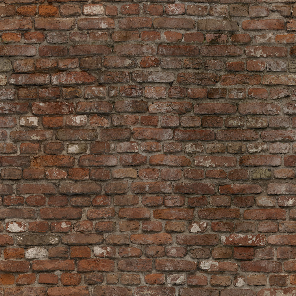
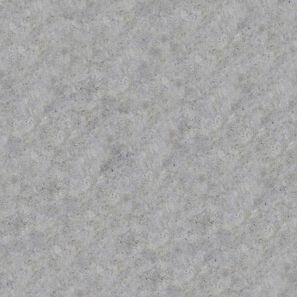
Now we need to determine areas where the brick will show through under the plaster. To do this, select the wall and turn on Surface Custom Texture in the Surfaces section of the Parameters window. In the Texture field, first try to assign the standard textures: white.texture and black.texture. You will notice that in one case the wall is completely plastered, and in the second case it a solid brick wall. Now let's create our own mask for this surface — click + to add a new texture.

Set the required size, select R (single-channel mask) in Channels, click OK, and write wall_mask as the new texture name.
In the next section, we'll learn how to draw the mask directly on the object using the brush to mark the areas where we want to see brickwork. To do this, UNIGINE we'll use the Texture Editor tool.
The information on this page is valid for UNIGINE 2.19.1 SDK.
