Sky
Sky is an object used to recreate the atmosphere in the scene. It is modeled as an upper hemisphere of the specified color, tiled with clouds textures to produce plausible and inexpensive dynamic clouds. It can also have any cube map as a background picture.
Besides flat dynamic clouds, volumetric clouds with shadows can also be created within the object.
See Also
Creating Sky
To create the sky, perform the following steps:
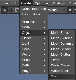
- On the Menu bar, click Create -> Object -> Sky.
- Place the sky object somewhere in the world.
- Specify the sky parameters.
Sky Parameters
| Spherical | Create the spherical sky dome. If the option is disabled, only the upper hemisphere will be created.
Notice
The sky is represented as the sky dome. To avoid the visual artifacts of the apparent curvature caused by applying the clouds texture, sphere is recommended to be flattened a bit (for detailed information see the sky_base material). |
|---|
Creating Volumetric Clouds
For cases when the camera is free roaming in the sky, the volumetric clouds with a high physical fidelity can be created.

Rendering Technique
To visualize the clouds, the slice-based volume rendering technique is used. It is provided through the following:
- The volume data is stored in the memory as a 3D texture in the RG8 format, so it can be easily loaded to the texture memory of the GPU.
- At the rendering time, 3D texture of the volume data is mapped inside the volume bounding box, and then the slices of planes called proxy geometry are computed, which are clipped against the bounding box and oriented orthogonally to the viewing direction.
- Since the view-aligned proxy geometry slices are not typically aligned to the texture's slices, GPU samples the texture using bilinear interpolation to gain the pixel color values, and renders each slice as a textured polygon. The planes are drawn in back-to-front order and the result is blended into the frame buffer.
 Rendering view-aligned proxy geometry by sampling 3D texture
The clouds self-shadowing is computed by means of ray tracing that samples the cloud volume density (stored in voxels). When the tracing is performed, the brightness of the ray traversing through the volume diminishes with each voxel, until finally all the voxels, further positioned on the path of that ray, are rendered shadowed.
Rendering volumetric clouds is quite a computationally expensive task: to simplify the load, clouds are completely computed within six frames , at the time using the image from the previous update, which effectively prevents lagging. This does not cause any detrimental visual effects.
Clouds Formation Parameters
In Unigine, the volumetric clouds are procedurally generated on the base of a physically-correct algorithm that considers atmospheric fluid dynamics. It characterizes the clouds' shapes and assures the natural and visually convincing clouds.
For realistic modeling this formation mechanisms, the cloud volume space is subdivided into lattice of cells that correspond to the voxels. Basing on the specified density mask data, three modulation parameters are assigned to each cell:
- Cloud defines if this cell is a cloud.
- Humidity level defines whether there is enough vapour in the cell to form a cloud.
- Phase transition defines whether a phase transition from vapour to water (cloud) is ready to occur.
The parameters are stored as logical variables determining if the condition is true or false (1 or 0 state). At each time step this factors introduce simple transition rules applied to the lattice and defining the cloud formation:
- The cell should have positive humidity level (1).
- If its neighboring cells are ready for phase transition, the cell in question also changes phase transition value for 1.
- After that, the cell becomes a cloud (while both humidity level and the phase transition become 0).
As described above, the result obtained by the binary distribution is a harsh one, because at each voxel it strictly defines presence or absence of the cloud. Therefore, before the going to the next step of rendering, the density at each point is calculated by smoothing the value.
| Humidity | A humidity probability factor changes the cell humidity level to 1 if the generated random number is less than the specified probability value. It results in the following:
|
|---|---|
| Transition | A phase transition probability state of the cell changes to 1 if the generated random number is less than the specified phase transition probability. Tweaking will produce the following:
|
| Extinction | Extinction of the clouds is done in the following way:
|
Density Mask
A density mask is used as a base for procedural generation of the natural-looking clouds. It represents a layered texture, each layer of which reproduces a decreasing amount of cloud cover, so that their smooth and gradual interpolation will provide a persuasive cloud shaping with the emulated conditions.
The mask can either be a RGB8 or 3D texture that can contain layers with different cloud formation parameters. Channels of the mask set the following:
- Red channel sets the humidity level. The higher the channel value, the more clouds will be generated.
- Green channel sets the readiness of the phase transition to form the cloud from vapor. The higher the channel value, the more probable it is that clouds will be generated in this point.
- Blue channel sets extinction probability for clouds. The higher the channel value, the less clouds will be rendered in this point leaving the sky clear.
")
| Layer | This parameter allows you to choose the exact layer of the density mask to form the clouds, depending on the desired visual effect. The number of available layers depends on the mask.
It is also possible to select not only one layer, but to morph layers into each other with the time by setting Z-shift for clouds velocity. |
|---|
Clouds Velocity
The pilgrim clouds rarely stand still, they can calmly hover up in the sky or scud with the air blasts. Velocity parameter brings dynamics to the rendered image imitating wind in the clouds:
- The first two slots define the shift of the density image along the X and Y coordinates correspondingly, and provide the horizontal clouds drift. The intensity of the latter depends on the specified velocity value. It should be noted, that only the current layer of the density image is shifted.
- The third slot controlling the Z coordinate results in the successive shifting of all the density image layers. The clouds will subtly segue into another layer form.
Compared to the simple texture shifting (available via the Materials settings), the velocity Z-shift also modifies the shape of the clouds and grants their more natural and diverse distribution under the wind.
Clouds Size
Clouds greatly vary in structure and composition. With the size option defining the clouds length along three axes, the clouds can grow to towering mass or contract to delicate, wispy and feathery looking.
The size is set along the
X, Y and Z axes, respectively.
| Min slices | Minimum slices parameter allows optimizing rendering of clouds. It limits the number of cloud slices rendered when the camera is within the clouds bounding box. When looking from inside of clouds, only the nearest slices are actually seen (depending on the density of clouds), while limiting the number of slices allows to reducing the rendering time and increasing the performance. By default, the minimum number of slices is equal to 256.
The minimum number of slices will gradually increase up to the maximum number as the player moves away from the clouds. |
|---|---|
| Max slices | Maximum slices parameter sets the number of cloud slices rendered when the camera is outside the clouds bounding box. It allows limiting the number of rendering slices when the player is looking at the clouds from beneath of from above. By default, the maximum number of slices is equal to 512. |
Simulation
Enabling the simulation option allows simulating volumetric clouds in the background, when a volume surface is disabled or no material is assigned to it. When the weather is controlled by Tracker, clouds are enabled and rendered much faster, since all required calculations are already done.
Shadows from Clouds
To gain visual integrity of the rendered scene, the clouds should naturally dim the sun light. Enabling this surface allows them to cast dynamic shadows on the underlying ground, that match the sky dome clouds pattern. Mapping the same texture secures the shadows of varying intensity and precise placement.

The intensity of the cast shadows can be regulated by the shadow multiplier parameter in the sky_base material.