设置细节层次
 Using Levels of Details (LODs) is the main way to optimize your project. The point is to switch the high detailed mesh to a mesh with lower number of details when the mesh is far from camera. For that, you need to take your detailed model and create several versions of it, each with lower polygon count.使用详细程度(LODs) 是优化项目的主要方式。关键是当网格远离相机时,将高细节网格切换到细节数量较少的网格。为此,您需要获取详细模型并创建多个版本,每个版本的多边形数量都较少。
In UNIGINE, a model with LODs can be represented as a single Mesh object with a number of surfaces representing LODs. LODs settings allow you to specify the distance when a surface should be switched to another.在 UNIGINE 中,具有 LOD 的模型可以表示为具有多个表面代表 LOD。 LOD 设置允许您指定表面应切换到另一个表面时的距离。
LODs can be configured in one of the following ways:可以通过以下方式之一配置 LOD:
- Automatically when importing the model into UNIGINE.自动地将模型导入 UNIGINE 时。
- Manually by means of a 3D editor and UnigineEditor.手动通过 3D 编辑器和 UnigineEditor。
See Also也可以看看#
- The Levels of Details section of the article on World Management这详细程度世界管理文章的部分。
- The Surfaces tab of the Content Profiler tool to monitor surface LODs by toggling Min/Max Visibility and Min/Max Fade filtersContent Profiler 工具的 Surfaces 选项卡,用于监控曲面负载 (通过切换 Min/Max Visibility 和 Min/Max Fade 过滤器)
Automatic LODs Setting自动 LOD 设置#
Automatic LODs setting implies that LODs for the model are assigned and configured on its importing into UNIGINE.自动 LOD 设置意味着模型的 LOD 在导入 UNIGINE 时被分配和配置。
Automatic LODs setting can be found in the  Content Optimization video tutorial and the dedicated quick guide.自动 LOD 设置可以在Content 优化视频教程和专用快速指南.
When importing the model, you can choose one of the following options:导入模型时,您可以选择以下选项之一:
- Automatically generate LODs by UNIGINE. In this case, you only need your high-poly model - the Engine will do the rest.通过 UNIGINE自动生成LOD。在这种情况下,您只需要您的高多边形模型 - 引擎会完成剩下的工作。
- Use the name postfixes to specify LODs. In this case, you should previously prepare different meshes for different LODs of your model in a third-party software.使用名称后缀来指定 LOD。在这种情况下,您应该事先在第三方软件中为模型的不同 LOD 准备不同的网格。
Generating LODs Automatically自动生成 LOD#
UNIGINE enables you to automatically generate LODs for your high-poly model right when importing it, saving you a lot of time cause now you don't have to prepare levels of detail manually in some third-party software. The feature is based on the meshoptimizer library.
UNIGINE 使您能够在导入时自动为您的高多边形模型生成 LOD,从而为您节省大量时间,因为现在您不必在三分之一的时间内手动准备细节级别-派对软件。该功能基于 meshoptimizer 库。
To automatically generate LODs on importing the model into UNIGINE, simply drag it to the Asset Browser and perform the following:要在将模型导入 UNIGINE 时自动生成 LOD,只需将其拖到 Asset Browser 并执行以下操作:
-
In the import settings window, choose Auto-Generated in the Use LODs drop-down list.在导入设置窗口中,在 Use LODs 下拉列表中选择 Auto-Generated。
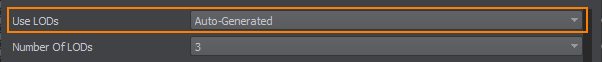
- Set the required number of LODs. For example, we will generate 3 LODs.设置所需的 LOD 数量。例如,我们将生成 3 LOD。
-
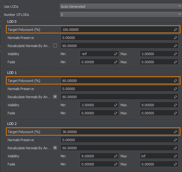
Specify the Target Polycount (%) value for each LOD. It defines the degree of geometry simplification for each LOD.为每个 LOD 指定 Target Polycount (%) 值。它定义了每个 LOD 的几何简化程度。
- For LOD 0, leave the default value of 100 percent.对于 LOD 0,保留默认值 100 百分比。
- For LOD 1, set the 60 percent of the original number of polygons.对于 LOD 1,设置原始多边形数的 60 百分比。
- For LOD 2, set the 30 percent of the original number of polygons.对于 LOD 2,设置原始多边形数的 30 百分比。
-
Specify the minimum and maximum visibility distances for each LOD. Maximum visibility distance of each LOD should be equal to the minimum visibility distance of the next LOD. Maximum visibility distance of the last LOD should be equal to inf.为每个 LOD 指定最小和最大 visibility 距离。每个 LOD 的最大可见距离应等于下一个 LOD 的最小可见距离。最后一个 LOD 的最大可见距离应等于 inf。
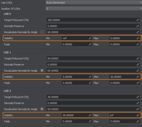
- For LOD 0, leave the default Min distance and set the Max distance at 5 units. It means that no matter how close the camera comes to the mesh, the surfaces will still be visible.对于 LOD 0,保留默认的 Min 距离并将 Max 距离设置为 5 单位。这意味着无论相机离网格有多近,表面仍然可见。
- For LOD 1, set the Min and Max distances at 5 and 30 units. It means that when the camera is 5 units away from the mesh, the first LOD surfaces won't be visible and the second LOD surfaces will be shown over the distance of 30 units.对于 LOD 1,将 Min 和 Max 距离设置为 5 和 30 单位。这意味着当相机距离网格 5 个单位时,第一个 LOD 表面将不可见,而第二个 LOD 表面将显示在 30 个单位的距离上。
- For LOD 2, set the Min distance at 30 units and leave the default Max distance. After 30 units, the second LOD surfaces won't be visible and the third LOD surfaces will be shown.对于 LOD 2,将 Min 距离设置为 30 单位,并保留默认的 Max 距离。 30 个单位后,第二个 LOD 表面将不可见,而将显示第三个 LOD 表面。
-
Specify the minimum and maximum fade distances for each LOD:为每个 LOD 指定最小和最大 fade 距离:
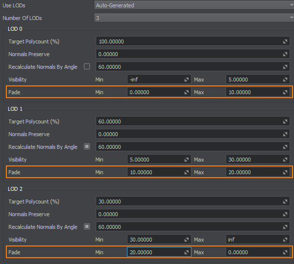
- For LOD 1, leave the default Min distance and set the Max distance to 10 units. It will prolong the distance over which the LOD surfaces are still visible and provide smooth fading.对于 LOD 1,保留默认的 Min 距离并将 Max 距离设置为 10 单位。它将延长 LOD 表面仍然可见的距离并提供平滑的淡入淡出。
- For LOD 2, set the Min distance to 10 units. After 5 up to 15 units, the second LOD surfaces will smoothly fade in. The Max distance set to 20 units. After 30 up to 50 units, the second LOD surfaces will smoothly fade out.对于 LOD 2,将 Min 距离设置为 10 单位。在 5 到 15 个单位之后,第二个 LOD 表面将平滑淡入。Max 距离设置为 20 单位。在 30 到 50 个单位之后,第二个 LOD 表面将平滑淡出。
- For LOD 3, set the Min distance to 20 units and leave the default Max distance. The third LOD surfaces will start to smoothly fade in from 30 to 50 units.对于 LOD 3,将 Min 距离设置为 20 单位并保留默认的 Max 距离。第三个 LOD 表面将开始从 30 到 50 单位平滑淡入。
- Leave the 0 value for the Normals Preserve option to ignore normals while simplifyign the mesh topology.为 Normals Preserve 选项保留 0 值以忽略法线,同时简化网格拓扑。
- Leave the default 60 value for the Recalculate Normals by Angle option.为 Recalculate Normals by Angle 选项保留默认的 60 值。
The Engine will generate and configure all LODs automatically using the specified settings.引擎将使用指定的设置自动生成和配置所有 LOD。
Combining LODs By Postfixes通过后缀组合 LOD#
If you prepare LODs in a third-party software, you can automatically assign and configure LODs of the model based on name postfixes.如果您在第三方软件中准备 LOD,您可以根据名称后缀自动分配和配置模型的 LOD。
Step 1. Export a Model From a Third-Party Software步骤 1. 从第三方软件导出模型#
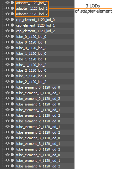
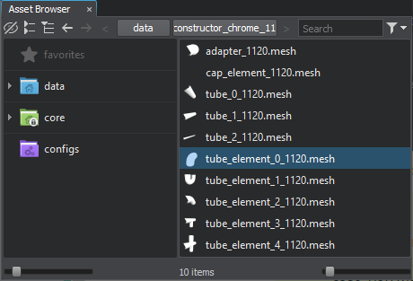
As an example, we will use the tubes_constructor_chrome_1120.fbx model from the Oil Refinery demo (available in UNIGINE SDK Browser). This FBX consists of several meshes, each of which represents an element of the tubes constructor.例如,我们将使用炼油厂演示中的 tubes_constructor_chrome_1120.fbx 模型(在 UNIGINE SDK 浏览器中可用)。这个 FBX 由几个网格组成,每个网格代表管道构造器的一个元素。
Perform the following in a 3D editor:在 3D 编辑器中执行以下操作:
-
Create several meshes for different LODs of your model: a detailed mesh for the closest LOD and a number of less detailed meshes for farther LODs.为模型的不同 LOD 创建多个网格:为最近的 LOD 创建一个详细的网格,为更远的 LOD 创建一些不太详细的网格。注意For example, for each mesh representing an element of the tubes constructor (10 meshes), there are 3 meshes representing LODs:例如,对于表示管构造器元素的每个网格(10 个网格),有 3 个网格表示 LOD:
- Export the meshes as an .fbx file.导出网格作为 .fbx 文件。
Step 2. Import Model to UNIGINE步骤 2. 将模型导入 UNIGINE#
To import the model into UNIGINE, drag and drop the previously exported FBX file to the Asset Browser and perform the following to automatically create LODs based on the name postfixes:要将模型导入 UNIGINE,请将之前导出的 FBX 文件拖放到 Asset Browser 并执行以下操作以根据名称后缀自动创建 LOD:
- Choose Combine By Postfixes in the Use LODs drop-down list.在 Use LODs 下拉列表中选择 Combine By Postfixes。
- Specify the maximum number of LODs stored in the FBX container (in our case, 3).指定存储在 FBX 容器中的 LOD 的最大数量(在我们的示例中为 3)。
-
For each LOD, define a postfix that will be used to group objects in an FBX file into a corresponding LOD.对于每个 LOD,定义一个后缀,用于将 FBX 文件中的对象分组到相应的 LOD。注意The postfix must be the same as the one used when creating objects in a 3D editor.后缀必须与使用的后缀相同在 3D 编辑器中创建对象.For the tubes constructor model, the following postfixes should be specified:对于 tube 构造函数模型,应指定以下后缀:
Names of generated surfaces will be as follows: material_name + LOD_postfix.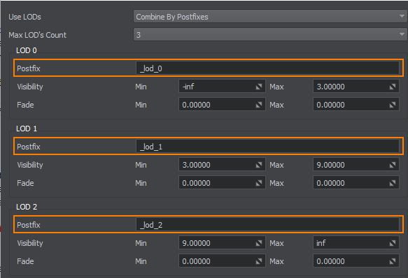
-
Specify the minimum and maximum visibility distances for each LOD. Maximum visibility distance of each LOD should be equal to the minimum visibility distance of the next LOD. Maximum visibility distance of the last LOD should be equal to inf.指定每个 LOD 的最小和最大可见距离。每个 LOD 的最大可见距离应等于下一个 LOD 的最小可见距离。最后一个 LOD 的最大可见距离应等于 inf。
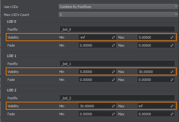
- For _lod_0, leave the default Min distance and set the Max distance at 5 units. It means that no matter how close the camera comes to the mesh, the surfaces will still be visible.对于 _lod_0,保留默认的 Min 距离并将 Max 距离设置为 5 单位。这意味着无论相机离网格有多近,表面仍然可见。
- For _lod_1, set the Min and Max distances at 5 and 30 units. It means that when the camera is 5 units away from the mesh, the first LOD surfaces won't be visible and the second LOD surfaces will be shown over the distance of 30 units.对于 _lod_1,将 Min 和 Max 距离设置为 5 和 30 单位。这意味着当相机距离网格 5 单位时,第一个 LOD 表面将不可见,而第二个 LOD 表面将显示在 30 单位的距离上。
- For _lod_2, set the Min distance at 30 units and leave the default Max distance. After 30 units, the second LOD surfaces won't be visible and the third LOD surfaces will be shown.对于 _lod_2,将 Min 距离设置为 30 单位,并保留默认的 Max 距离。在 30 单位之后,第二个 LOD 表面将不可见,而将显示第三个 LOD 表面。
-
Specify the minimum and maximum fade distances for each LOD:指定每个 LOD 的最小和最大渐变距离:
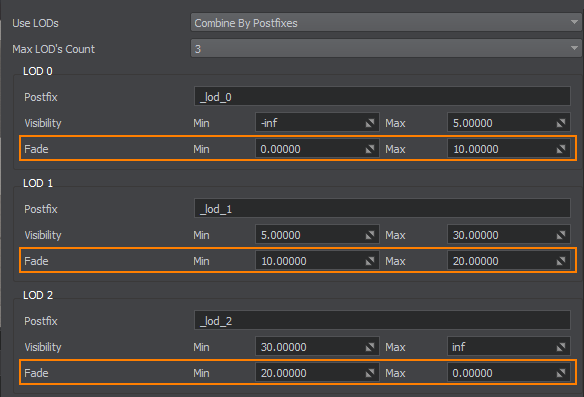
- For _lod_0, leave the default Min distance and set the Max distance to 10 units. It will prolong the distance over which the LOD surfaces are still visible and provide smooth fading.对于 _lod_0,保留默认的 Min 距离并将 Max 距离设置为 10 单位。它将延长 LOD 表面仍然可见的距离并提供平滑的淡入淡出。
- For _lod_1, set the Min distance to 10 units. After 5 up to 15 units, the second LOD surfaces will smoothly fade in. The Max distance set to 20 units. After 30 up to 50 units, the second LOD surfaces will smoothly fade out.对于 _lod_1,将 Min 距离设置为 10 单位。在 5 到 15 单位之后,第二个 LOD 表面将平滑淡入。Max 距离设置为 20 单位。在 30 到 50 个单位之后,第二个 LOD 表面将平滑淡出。
- For _lod_2, set the Min distance to 20 units and leave the default Max distance. The third LOD surfaces will start to smoothly fade in from 30 to 50 units.对于 _lod_2,将 Min 距离设置为 20 单位并保留默认的 Max 距离。第三个 LOD 表面将从 30 单位平滑淡入到 50 单位。
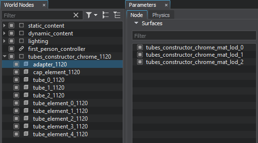
In the result, the FBX container with 10 meshes will be imported. Each mesh will have 3 surfaces representing LODs.结果,将导入具有 10 个网格的 FBX 容器。每个网格将有 3 个表示 LOD 的表面。
Meshes of the Imported FBX导入的 FBX 的网格When working with large scenes, you cannot know for sure how many LODs some model will have. So, it is recommended to specify more LODs in the importer: in this case, you won't have to set up LODs manually, if the model contains more LODs than the previously imported one. For example, if you set up 10 LODs in the importer, you can import models with up to 10 LODs.在处理大型场景时,您无法确定某个模型将具有多少 LOD。因此,建议在导入器中指定更多的 LOD:在这种情况下,如果模型包含的 LOD 比之前导入的更多,则无需手动设置 LOD。例如,如果您在导入器中设置了 10 个 LOD,则最多可以导入具有 10 个 LOD 的模型。Step 3. Add Model to the World步骤 3. 将模型添加到世界#
Add an exported model into the world as described here. All LODs will be already created and set up according to the specified import values:将导出的模型添加到世界中这里描述.所有 LOD 都将根据指定的导入值创建和设置:
Imported Tubes Constructor with LODs带 LOD 的导入管构造器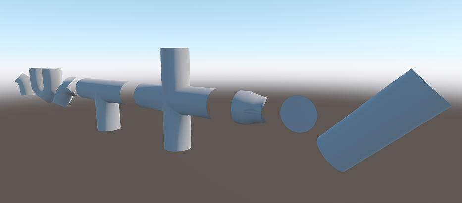
FBX Added to the WorldFBX 添加到世界If required, adjust the LODs surfaces in the Node tab of the Parameters window:如果需要,在 Parameters 窗口的 Node 选项卡中调整 LOD 表面:
- Configure the Min and Max Parent settings. In this tutorial, we use the default values of 1.配置 Min and Max Parent 设置。在本教程中,我们使用默认值 1。
Try to move the camera forward/backward to check how LODs are switched:尝试向前/向后移动相机以检查 LOD 的切换方式:
LODs SwitchingLOD 切换Manual LODs Setting手动 LOD 设置#
Manual LODs setting implies that LODs for the model are created in a third-party 3D editor and LODs parameters are adjusted when the model is already imported and added to the scene.手动 LOD 设置意味着模型的 LOD 是在第三方 3D 编辑器中创建的,并且在模型已经导入并添加到场景中时会调整 LOD 参数。
Manual LODs setting is also shown in the Content Optimization video tutorial.手动 LOD 设置也显示在内容优化视频教程。
Step 1. Export LODs步骤 1. 导出 LOD#
To export the mesh with LODs, do the following:要导出具有 LOD 的网格,请执行以下操作:
-
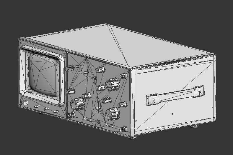
In your 3D editor, create a detailed model and a number of models with a low number of polygons. For example, you can just copy the existing detailed model and reduce the number of polygons.在您的 3D 编辑器中,创建一个详细的模型和一些具有少量多边形的模型。例如,您可以只复制现有的详细模型并减少多边形的数量。注意You should create a separate LOD for each part of the model to which a unique material is assigned.您应该为分配了唯一材质的模型的每个部分创建单独的 LOD。As an example, we will use the model of an oscilloscope from Superposition benchmark (available via UNIGINE SDK Browser). This model already contains 3 LODs.例如,我们将使用来自叠加基准测试的示波器模型(可通过 UNIGINE SDK Browser 获得)。该模型已经包含 3 个 LOD。
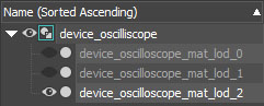
10109 polygons 5004 polygons 2583 polygons 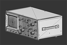
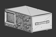
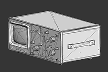 LOD 0LOD 1LOD 2
 - Generate LODs according to a pipeline used by your 3D editor. For example, in 3ds Max, you should group meshes representing LODs and then create LODs via the Level of Detail utility.根据 3D 编辑器使用的管道生成 LOD。例如,在 3ds Max 中,您应该对表示 LOD 的网格进行分组,然后通过 Level of Detail 实用程序创建 LOD。
- Export the model with LODs as an *.fbx file.将具有 LOD 的模型导出为 *.fbx 文件。


Step 2. Import Model to UNIGINE步骤 2. 将模型导入 UNIGINE#
To import the model into UNIGINE:到导入模型进入UNIGINE:
- Click Import in the Asset Browser and choose the exported FBX file.单击 Asset Browser 中的 Import 并选择导出的 FBX 文件。
- In the Import FBX window, enable the Merge Static Meshes option. Otherwise, LODs will be imported as separate meshes, not surfaces.在 Import FBX 窗口中,启用 Merge Static Meshes 选项。否则,LOD 将作为单独的网格而不是曲面导入。
- Import the model.导入模型。
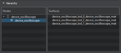
If you select the imported FBX, its content will be previewed in the Hierarchy section of the Parameters window.如果选择导入的 FBX,其内容将在 Parameters 窗口的 Hierarchy 部分预览。
Step 3. Add a Model to the World步骤 3. 向世界添加模型#
Add an exported model into the world as described here. By default, all surfaces (LODs) are visible at the same time:将导出的模型添加到世界中这里描述.默认情况下,所有表面 (LOD) 都是同时可见的:
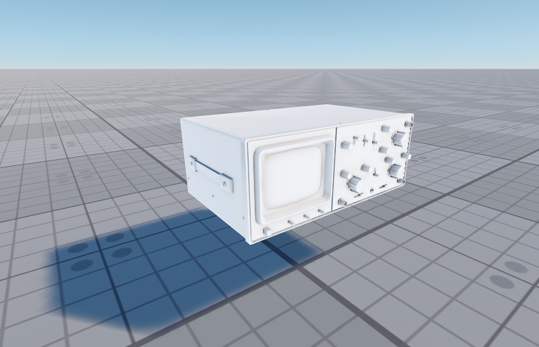
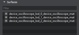
Oscilloscope Model示波器型号The surfaces of the exported model that represent LODs can be found in the Node tab of the Parameters window:可以在 Parameters 窗口的 Node 选项卡中找到表示 LOD 的导出模型的表面:
Step 4. Set Up LODs第 4 步:设置 LOD#
This section explains how to set up LODs of the mesh to smoothly switch a high detailed LOD to a low detailed when the camera begins to move away from the mesh. LOD surfaces have 3 parameters:本节介绍如何设置网格的 LOD,以便在相机开始远离网格时平滑地将高细节 LOD 切换到低细节。 LOD 表面有 3 个参数:
The chapter contains the example values of the parameters. You can specify your own ones, if necessary.本章包含参数的示例值。如有必要,您可以指定自己的。Visibility and Fade Distances可见性和淡化距离#
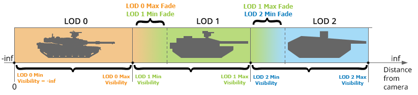
For each LOD surface, you should specify a visibility distance and a fade distance. The following image illustrates these distances and how they work.对于每个 LOD 表面,您应该指定可见距离和淡入淡出距离。 下图说明了这些距离及其工作原理。
For setting up the LOD surfaces, do the following:要设置 LOD 表面,请执行以下操作:
- Open the World Hierarchy window, and choose the added node.打开世界等级窗口,然后选择添加的节点。
-
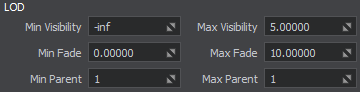
In the Surfaces group of the Node tab (the Parameters window), choose the first LOD surface:在 Node 选项卡(Parameters 窗口)的 Surfaces 组中,选择第一个 LOD 曲面:
- Set its Maximum Visibility distance to 5. It means that when the camera is 5 units away from mesh, the first LOD surfaces won't be visible.将其 Maximum Visibility 距离设置为 5。这意味着当相机距离网格 5 个单位时,第一个 LOD 表面将不可见。
- Leave the Minimum Visibility distance at -inf. It means that no matter how close the camera comes to the mesh, the surfaces will still be visible.将 Minimum Visibility 距离保留为 -inf。这意味着无论相机离网格有多近,表面仍然可见。
- Set the Maximum Fade distance to 10 units. It will extend the distance over which the LOD surfaces are still visible and provide smooth fading.将 Maximum Fade 距离设置为 10 单位。它将延长 LOD 表面仍然可见的距离并提供平滑的淡入淡出。
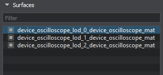
 注意You can disable other LOD surfaces to see the result of the current LOD surface settings.您可以禁用其他 LOD 表面以查看当前 LOD 表面设置的结果。
 -
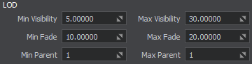
Choose the second LOD surfaces and:选择第二个 LOD曲面并:
- Set the Minimum Visibility distance of the second LOD surfaces to start exactly where the Maximum Visible distance of the first LOD surfaces ends: at 5 units. It means that when the first LOD surfaces begin to fade out, the second LOD surfaces will be shown.将第二个 LOD 曲面的 Minimum Visibility 距离设置为恰好从第一个 LOD 曲面的 Maximum Visible 距离结束的位置开始:以 5 为单位。这意味着当第一个 LOD 表面开始淡出时,将显示第二个 LOD 表面。
- Set the Maximum Visibility distance at 30 units. After 30 units, the second LOD surfaces begin to fade out and the third LOD surfaces will be shown.将 Maximum Visibility 距离设置为30个单位。 30 个单位后,第二个 LOD 表面开始淡出,并显示第三个 LOD 表面。
- Set the Minimum Fade distance to 10 units. After 5 up to 15 units, the second LOD surfaces will smoothly fade in.将 Minimum Fade 距离设置为 10 单位。在 5 到 15 个单位之后,第二个 LOD 表面将平滑淡入。
- Set the Maximum Fade distance to 20 units. After 30 up to 50 units, the second LOD surfaces will smoothly fade out.将 Maximum Fade 距离设置为 20 单位。在 30 到 50 个单位之后,第二个 LOD 表面将平滑淡出。
- Choose the third LOD surfaces and:
- Set the Minimum Visibility distance to 30 units. It means that when the second LOD surfaces begin to disappear, the third LOD surfaces will be shown.Set the Minimum Visibility distance to 30 units. It means that when the second LOD surfaces begin to disappear, the third LOD surfaces will be shown.
- Set the Maximum Visibility distance at 300 units. After 300 units the third LOD surfaces totally disappear.Set the Maximum Visibility distance at 300 units. After 300 units the third LOD surfaces totally disappear.
- Set the Minimum Fade distance to 20 units. The third LOD surfaces will start to smoothly fade in from 30 to 50 units.Set the Minimum Fade distance to 20 units. The third LOD surfaces will start to smoothly fade in from 30 to 50 units.
-
Set the Maximum Fade distance to 50 units. After 300 units, the mesh will begin to smoothly fade out.Set the Maximum Fade distance to 50 units. After 300 units, the mesh will begin to smoothly fade out.注意If you want to leave the last LOD surface always visible, set the Maximum Visibility distance to inf.If you want to leave the last LOD surface always visible, set the Maximum Visibility distance to inf.
Set the Minimum Visibility distance to 30 units. It means that when the second LOD surfaces begin to disappear, the third LOD surfaces will be shown.Set the Maximum Visibility distance at 300 units. After 300 units the third LOD surfaces totally disappear.Set the Minimum Fade distance to 20 units. The third LOD surfaces will start to smoothly fade in from 30 to 50 units.Set the Maximum Fade distance to 50 units. After 300 units, the mesh will begin to smoothly fade out.If you want to leave the last LOD surface always visible, set the Maximum Visibility distance to inf.选择第三个 LOD表面并且: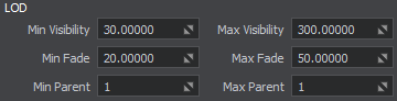
- Set the Minimum Visibility distance to 30 units. It means that when the second LOD surfaces begin to disappear, the third LOD surfaces will be shown.将 Minimum Visibility距离设置为 30 单位。这意味着当第二个 LOD 表面开始消失时,将显示第三个 LOD 表面。
- Set the Maximum Visibility distance at 300 units. After 300 units the third LOD surfaces totally disappear.将 Maximum Visibility距离设置为 300 单位。 300 个单位后,第三个 LOD 表面完全消失。
- Set the Minimum Fade distance to 20 units. The third LOD surfaces will start to smoothly fade in from 30 to 50 units.将 Minimum Fade距离设置为 20 单位。第三个 LOD 表面将开始从 30 到 50 个单位平滑淡入。
-
Set the Maximum Fade distance to 50 units. After 300 units, the mesh will begin to smoothly fade out.将 Maximum Fade距离设置为 50 单位。 300 个单位后,网格将开始平滑淡出。注意If you want to leave the last LOD surface always visible, set the Maximum Visibility distance to inf.如果要让最后一个 LOD 表面始终可见,请将最大可见距离设置为 inf。
You should specify the same settings for each surface of the same LOD (if any). Different surfaces from one level of details should have the same settings to appear and disappear simultaneously.您应该为同一 LOD(如果有)的每个表面指定相同的设置。一个细节层次的不同表面应该具有相同的设置以同时出现和消失。
Minimum and Maximum Parents最小和最大父母#
Another important parameters of the LODs are Min Parent and Max Parent.LOD 的另一个重要参数是 Min Parent and Max Parent。
These parameters enable you to specify to which surface or node up in the hierarchy the minimum and maximum visibility distances will be measured. Use the default values of 1. In this case, all surfaces of the mesh will be switched simultaneously, because their distances will be measured not to surfaces themselves, but to the bounding box of the whole mesh.这些参数使您能够指定将测量最小和最大可见距离到层次结构中的哪个表面或节点。使用默认值 1。在这种情况下,网格的所有表面将同时切换,因为它们的距离不是测量到表面本身,而是测量到整个网格的边界框。